


拼接光栅的大光斑连续位移测量
Continuous displacement measurement of large spot with stitched gratings
doi: 10.37188/CO.EN-2025-0023
-
摘要:
拼接光栅是实现光栅位移量程拓展的重要方法,但拼缝和拼接误差的存在导致无法实现高精度连续的位移测量。因此,本文提出一种改进的拼接光栅位移测量方法,通过大光斑抑制方法减少拼缝过程中光信号强度的损失,利用波前梯度调制技术保证连续位移测量,建立拼接光栅波前与位移测量误差的映射理论模型,并使用单侧利特罗光路进行连续位移测量实验验证。实验结果表明,在满足波前梯度指标的前提下,理论模型误差与实际测量残差之间线性相关度大于0.9,修正后连续位移测量残差小于50 nm。充分验证了该方法能够实现高精度连续位移测量,高稳定的量程拓展,为光栅位移测量领域提供了新的量程拓展思路。
Abstract:Stitched gratings provide an important method to extend the grating displacement measurement range. However, the existence of stitched seams and stitching errors prevents high-precision continuous displacement measurement. This paper proposes an improved stitched grating displacement measurement method. The method reduces light signal intensity loss during stitching via a large spot suppression technique, ensures continuous displacement measurement using wavefront gradient modulation technology, establishes a theoretical model of the mapping between the stitched grating wavefront and the displacement measurement error, and verifies continuous displacement measurements experimentally using a single-sided Littrow optical path. Experimental results show that, based on the premise of matching the wavefront gradient index, the linear correlation between the theoretical model error and the actual measurement residual is greater than 0.9, and the corrected continuous displacement measurement residual is less than 50 nm. This verifies that the proposed method can realize high-precision continuous displacement measurement and high-stability range extension in the grating displacement measurement field.
-
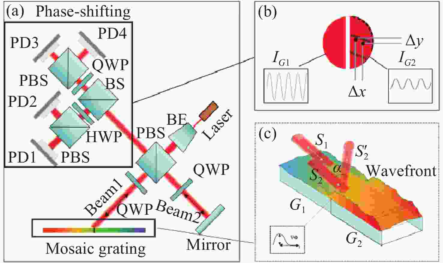
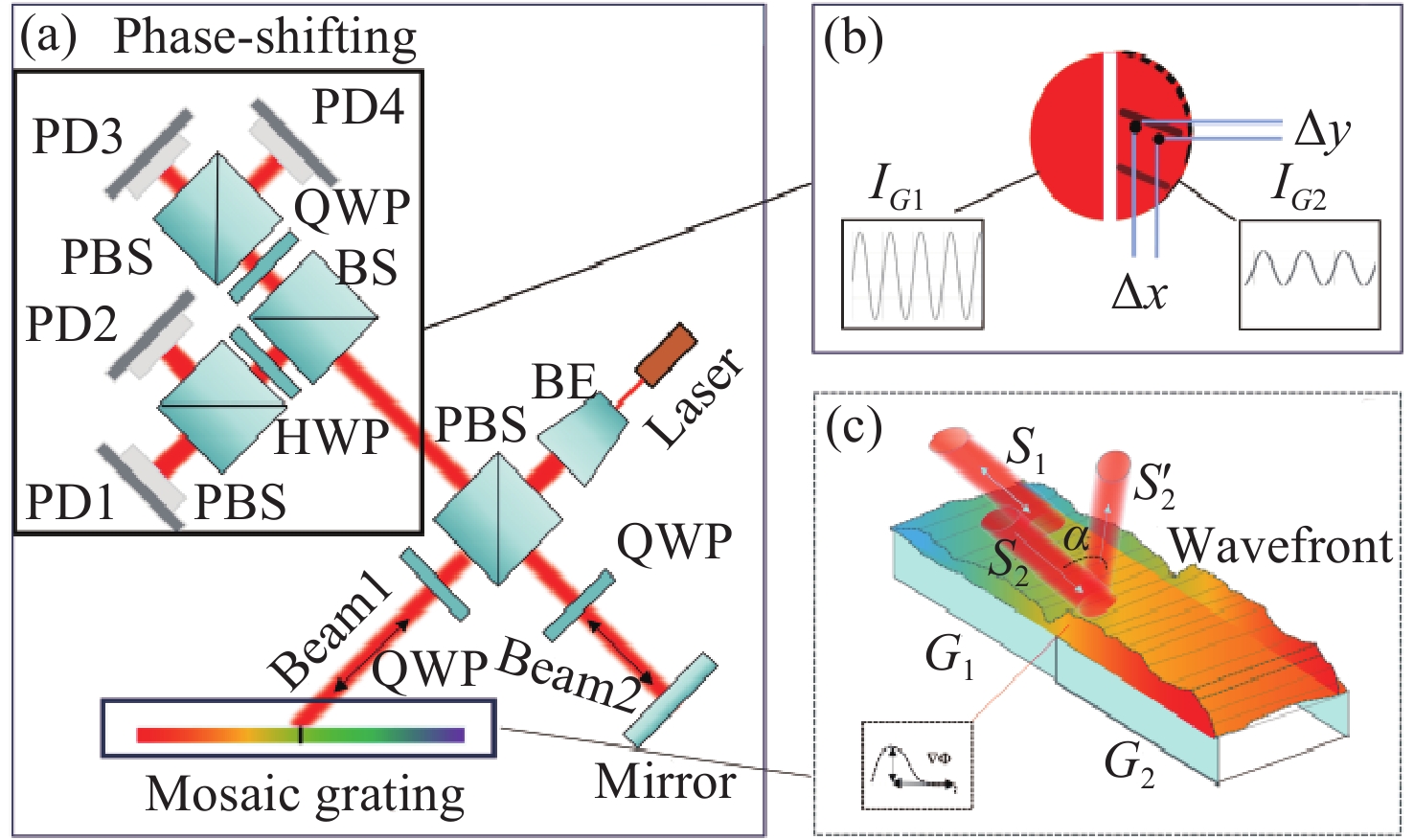
Figure 1. Optical path and error impact. (a) Schematic of the optical path. (b) Variation of the optical interference signal. (c) Wavefront gradient and angular offset.
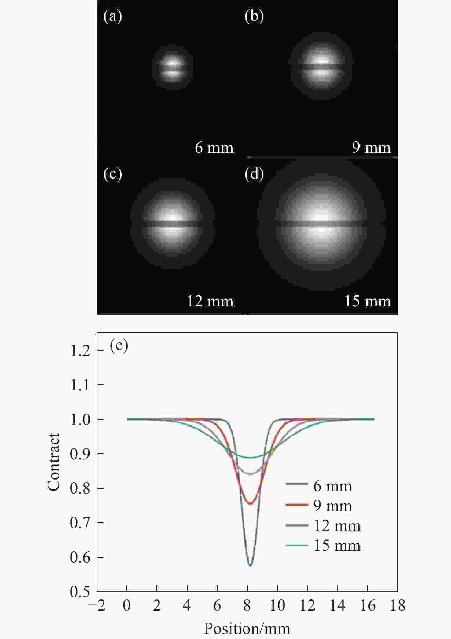
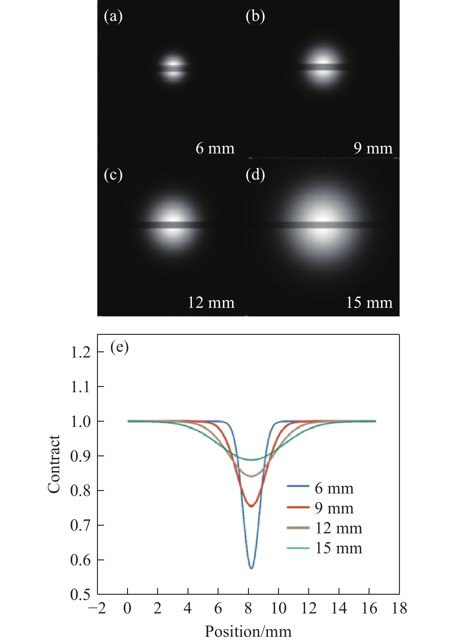
Figure 2. Schematic diagram of the receiving end with different spot sizes (a) Light intensity diagram for a 6mm diameter spot(b) 9mm diameter spot(c) 12mm diameter spot(d) 15mm diameter spot(e) Intensity attenuation across different spot sizes
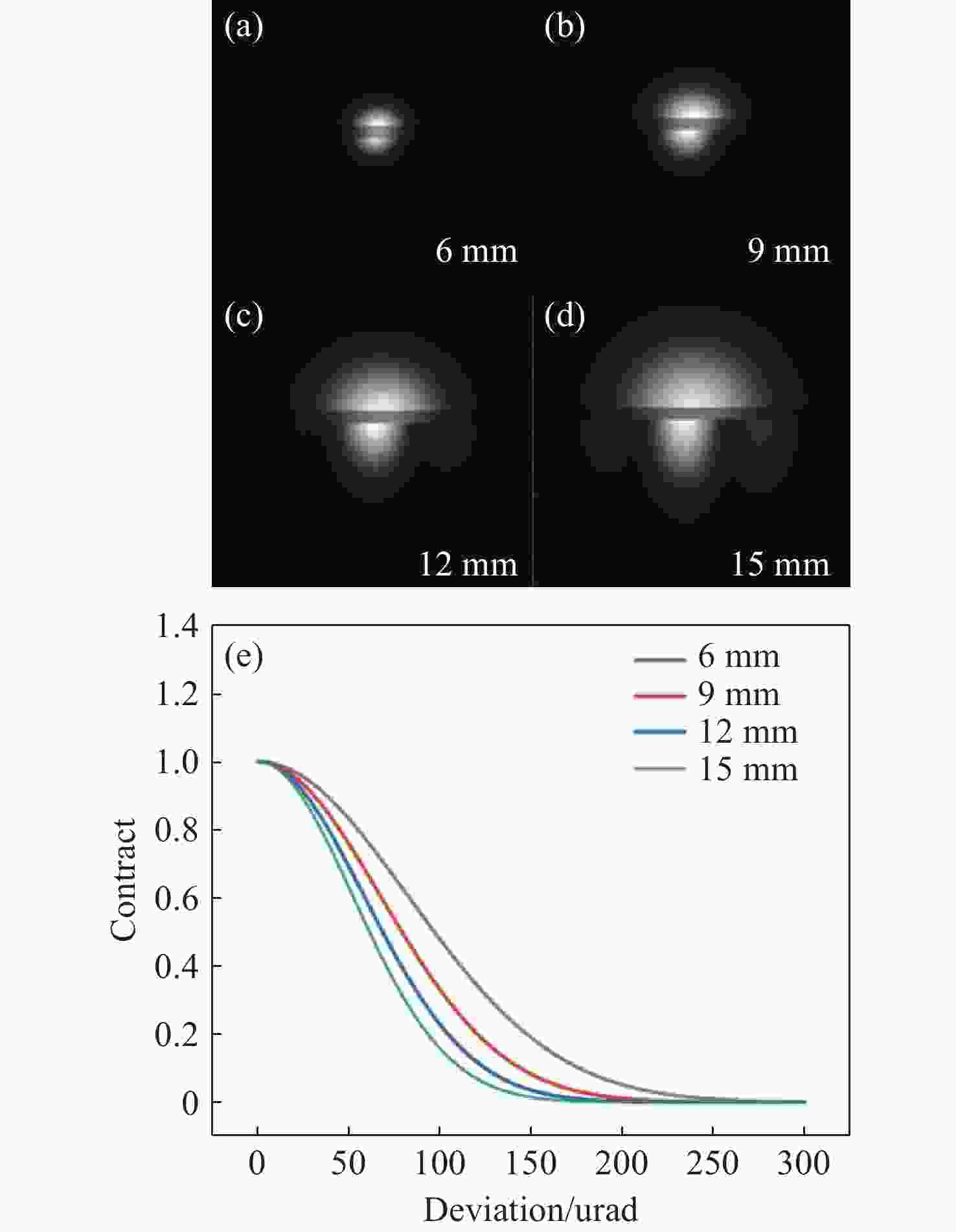
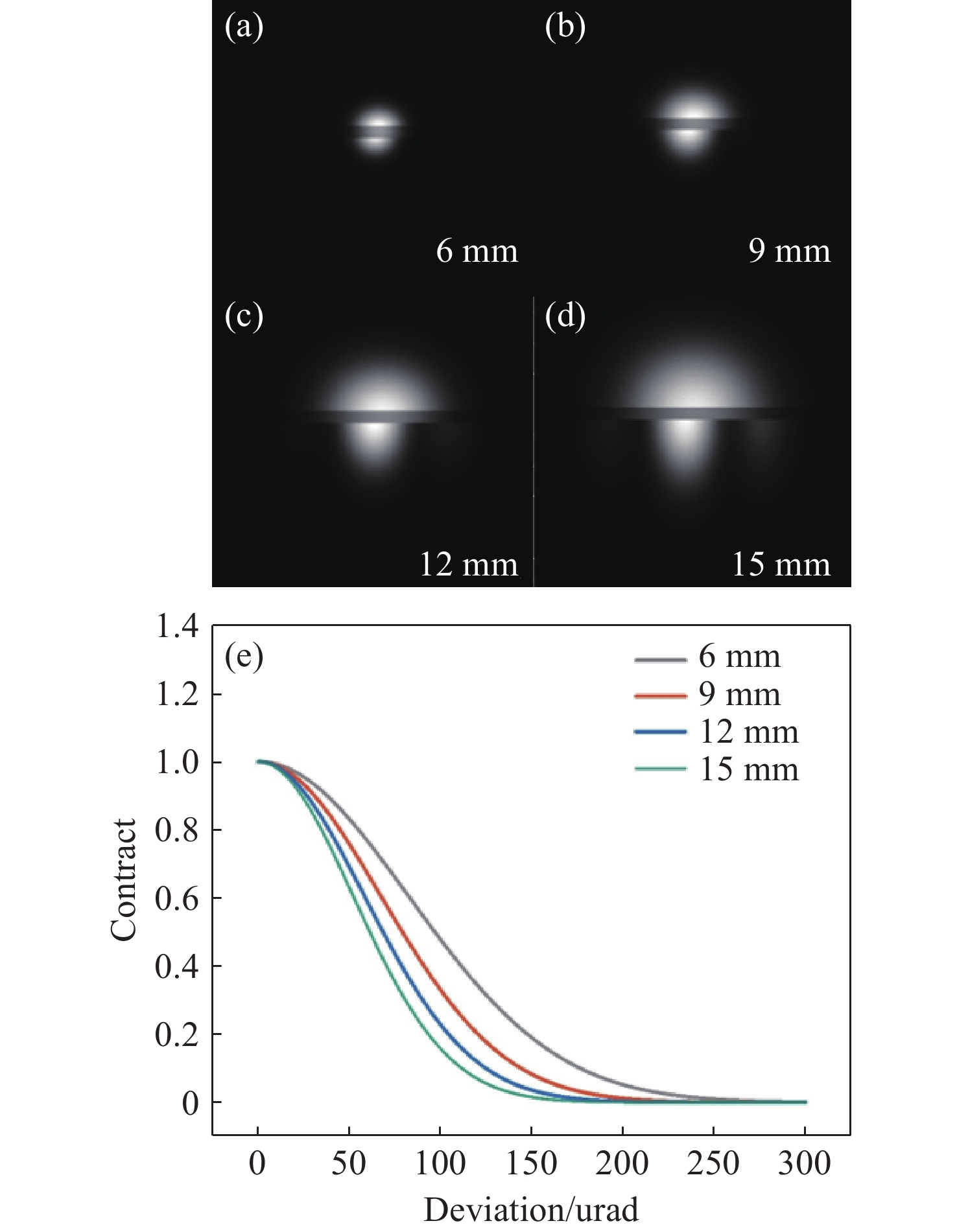
Figure 3. Impact of Beam Spot Size on Error Sensitivity (a) Beam spot diameter 6 mm with a fixed tilt angle of 0.005° (b) 9 mm (c) 12 mm (d) 15 mm (e) Error sensitivity of different beam spots
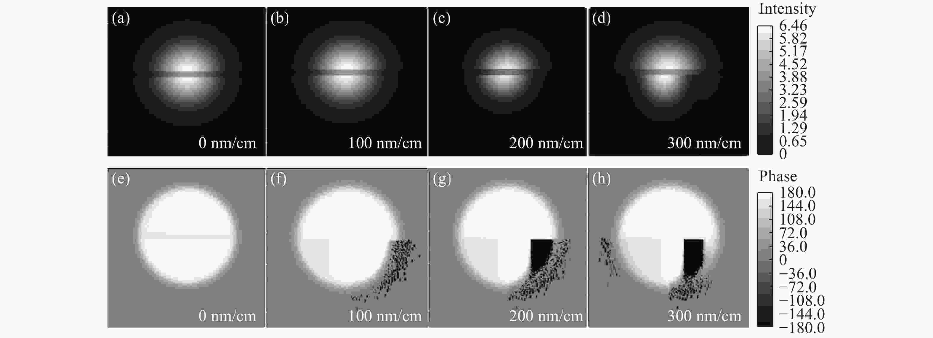
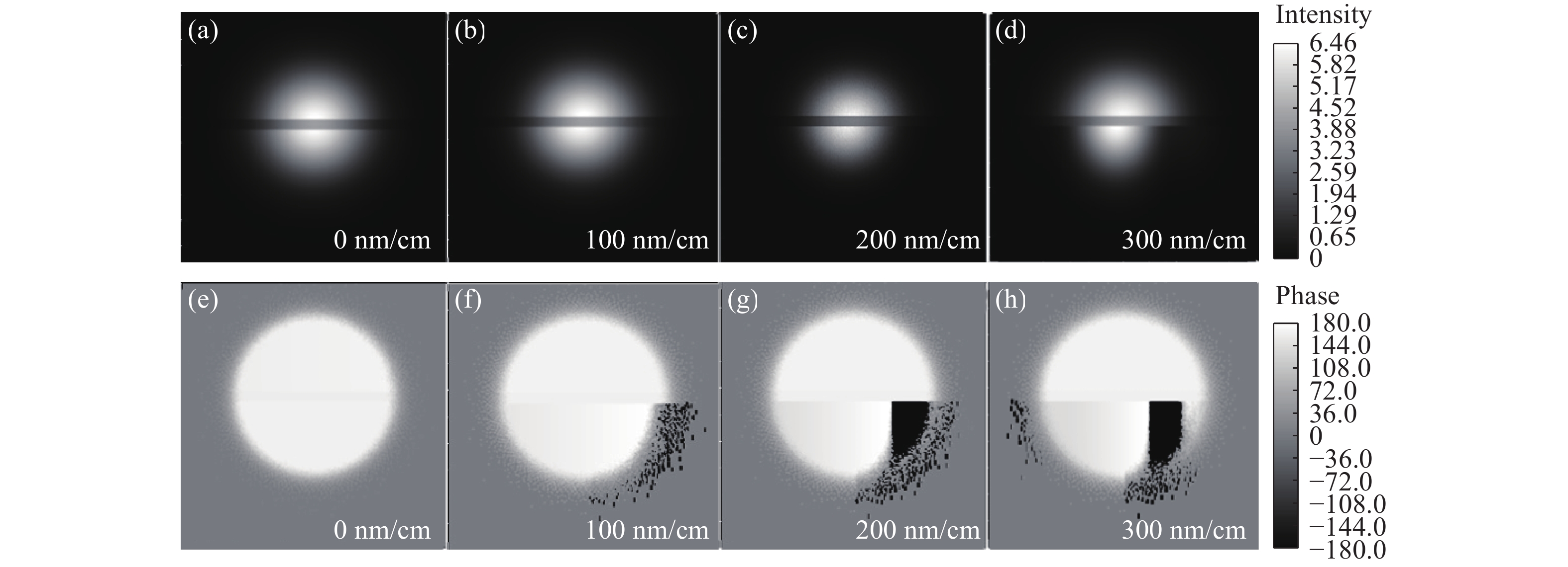
Figure 4. Schematic diagrams of beam spots with different stitching wavefront gradients(a) Schematic diagram of optical 100 nm/cm (b) 200 nm/cm (c) 300 nm/cm (d) 400 nm/cm (e) Phase variation with a wavefront gradient of 100 nm/cm (f) 200 nm/cm (g) 300 nm/cm (h) 400 nm/cm
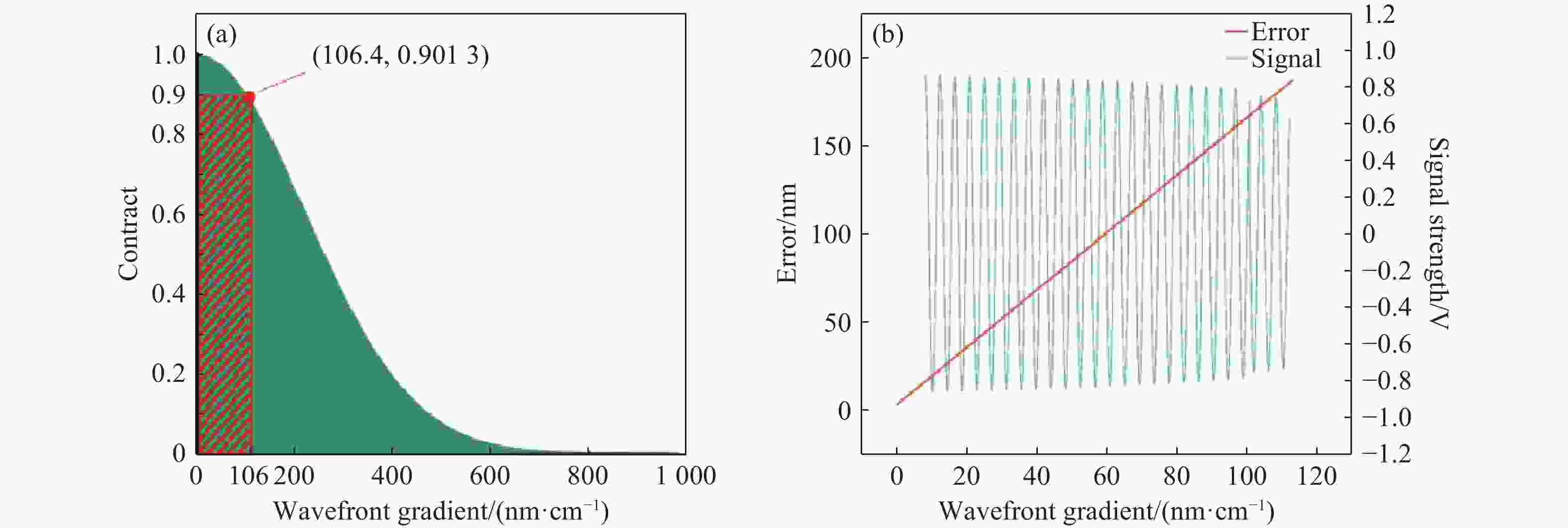
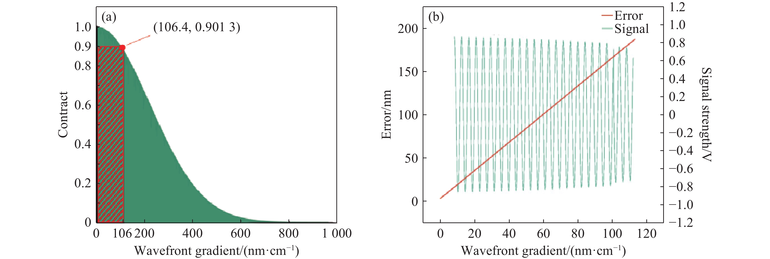
Figure 5. Schematic diagram of wavefront gradient-related simulations (a) Simulation of wavefront gradient and contrast mapping (b) Simulation of wavefront gradient and error mapping
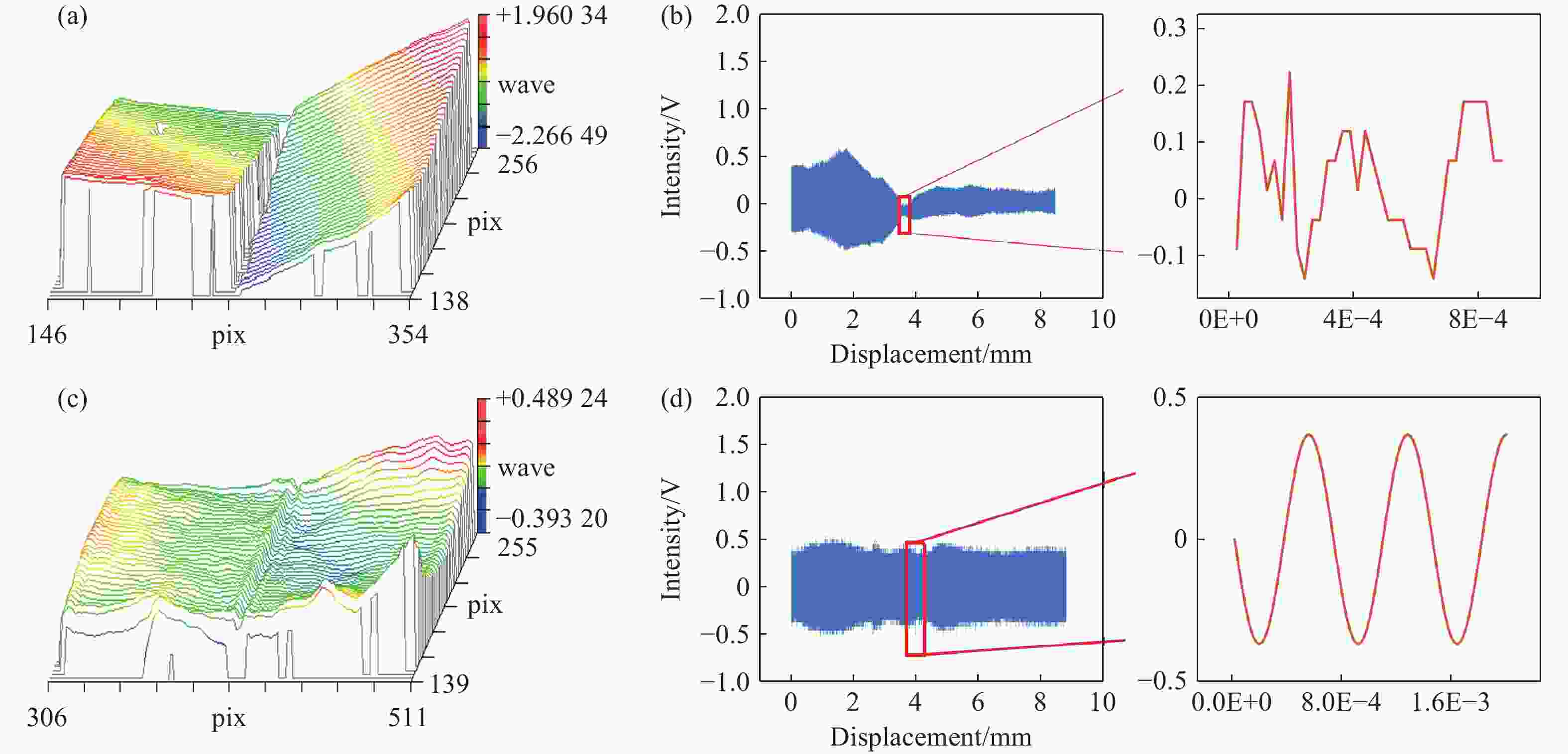
Figure 7. Stitched wavefront maps and wavefront signal comparison diagrams. (a) Large stitched wavefront gradient map. (b) Large stitched wavefront signal schematic. (c) Small stitched wavefront gradient map. (d) Small stitched wavefront signal schematic.
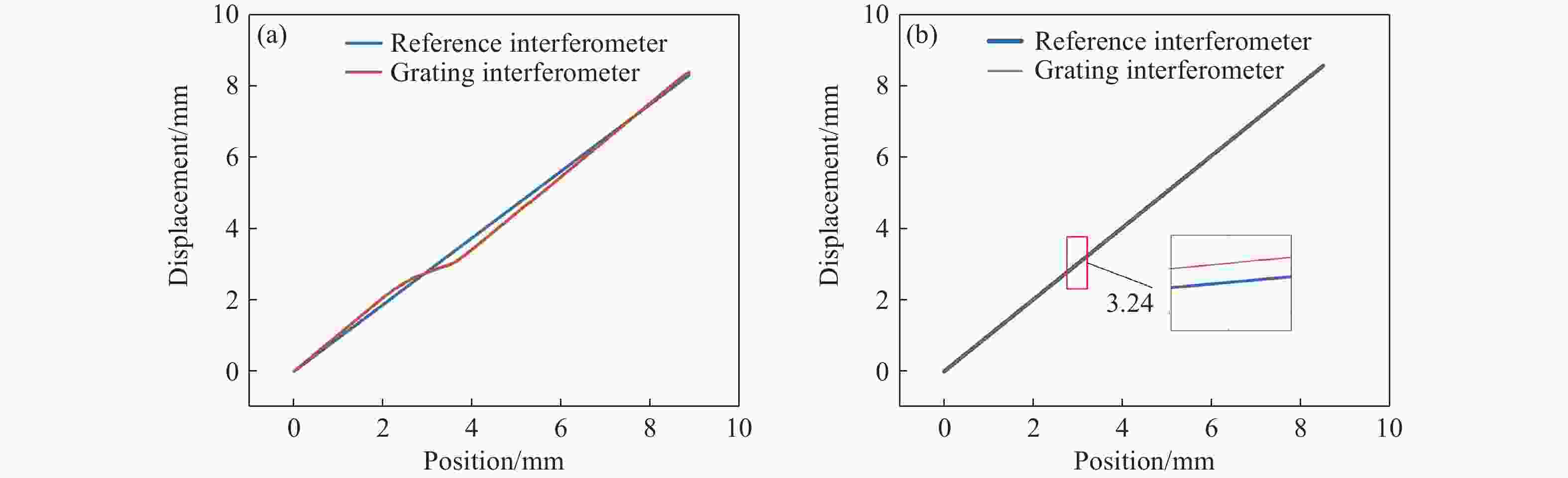
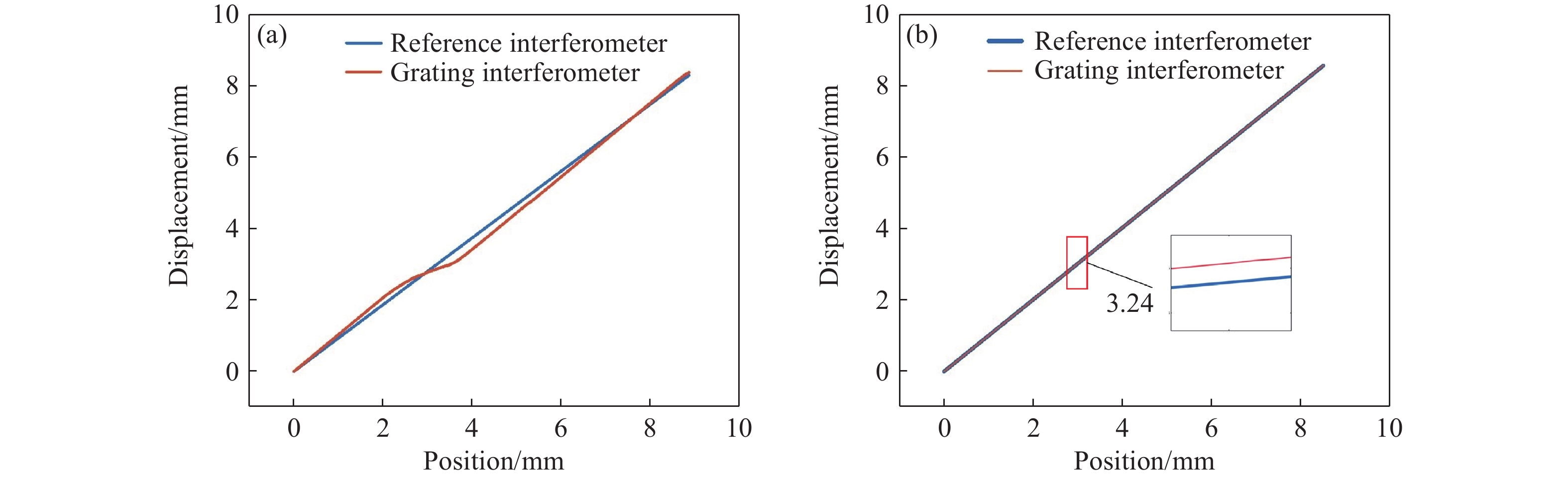
Figure 8. Comparison of data from the grating interferometer and the laser interferometer. (a) Comparison of displacement residuals with large wavefront gradient and (b) with small wavefront gradient.

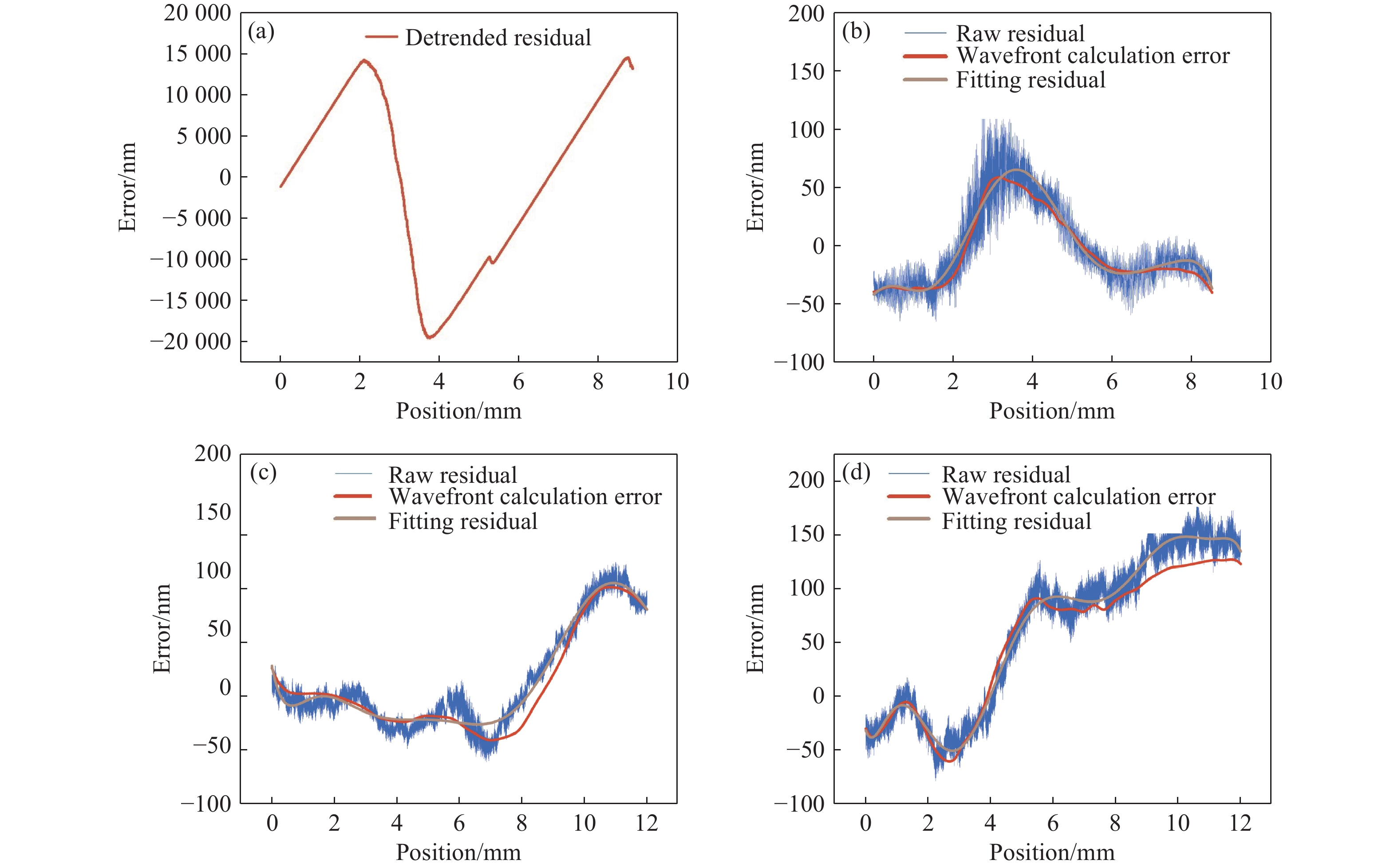
Figure 9. Wavefront displacement residuals. (a) Displacement residual diagram that does not meet the wavefront index requirements. Displacement residual diagrams of (b) Group 1, (c) Group 2, and (d) Group 3.
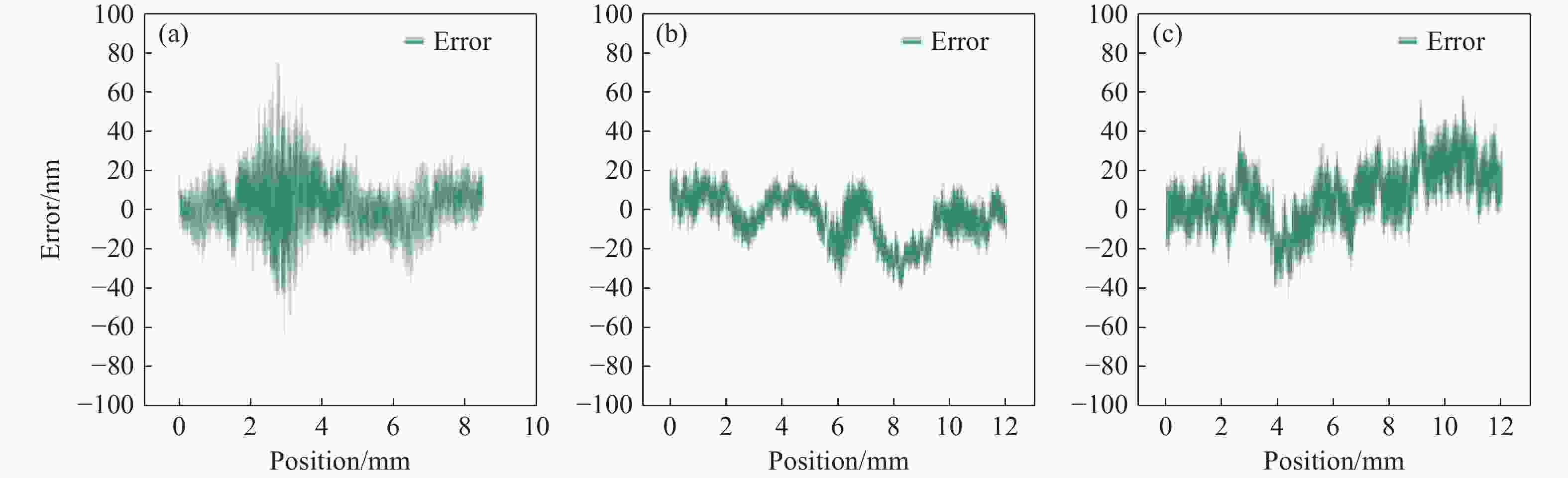
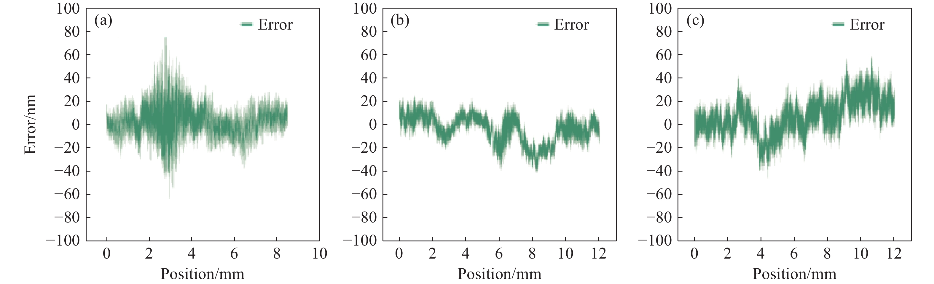
Figure 10. Error characteristics of the three groups after correction. (a) Group 1, (b) Group 2, and (c) Group 3.
Table 1. Linear Correlation Relationship between Residuals and the Calculated Curve
Group 1 Group 2 Group 3 Pearson 0.9127 0.9135 0.9527 Spearman 0.9035 0.9672 0w.9084  下载: 导出CSV
-
[1] GUO SH P, LU Z F, XIONG ZH, et al. Lithographic pattern quality enhancement of DMD lithography with spatiotemporal modulated technology[J]. Optics Letters, 2021, 46(6): 1377-1380. doi: 10.1364/OL.415788 [2] ZHU CH, ZHUANG Y Y, LIU B, et al. Review of fiber optic displacement sensors[J]. IEEE Transactions on Instrumentation and Measurement, 2022, 71: 7008212. [3] HU P CH, CHANG D, TAN J B, et al. Displacement measuring grating interferometer: a review[J]. Frontiers of Information Technology & Electronic Engineering, 2019, 20(5): 631-654. doi: 10.1631/FITEE.1800708 [4] YU H Y, CHEN X L, LIU CH J, et al. A survey on the grating based optical position encoder[J]. Optics & Laser Technology, 2021, 143: 107352. doi: 10.1016/j.optlastec.2021.107352 [5] ZHOU W Y, SUN Y J, LIU ZH W, et al. A random angle error interference eliminating method for grating interferometry measurement based on symmetry littrow structure[J]. Laser & Photonics Reviews, 2025, 19(11): 2401659. doi: 10.1002/lpor.202401659 [6] LI W H, WANG X Y, BAYANHESHIG, et al. Controlling the wavefront aberration of a large-aperture and high-precision holographic diffraction grating[J]. Light: Science & Applications, 2025, 14(1): 112. [7] HUANG Q SH, JIA Q, FENG J T, et al. Realization of wafer-scale nanogratings with sub-50 nm period through vacancy epitaxy[J]. Nature Communications, 2019, 10(1): 2437. doi: 10.1038/s41467-019-10095-2 [8] LIU ZH W, JIANG SH, LI X T, et al. Precision measurement of X-axis stage mirror profile in scanning beam interference lithography by three-probe system based on bidirectional integration model[J]. Optics Express, 2017, 25(9): 10312-10321. doi: 10.1364/OE.25.010312 [9] BEYE M. Transient gratings with X-rays[J]. Nature Photonics, 2021, 15(7): 490-492. doi: 10.1038/s41566-021-00837-4 [10] ZHANG J W, JIRIGALANTU, YU SH, et al. Research on manufacturing technology of nanoimprinted grating[J]. Journal of Manufacturing Processes, 2024, 131: 891-909. doi: 10.1016/j.jmapro.2024.09.033 [11] WANG SH W, ZENG L J. Analysis and minimization of spacing error of holographic gratings recorded with spherical collimation lenses[J]. Optics Express, 2015, 23(5): 5532-5546. doi: 10.1364/OE.23.005532 [12] LU Y X, QI X D, MI X T, et al. Detection and calculation of mosaic grating error based on wavefront method[J]. Acta Optica Sinica, 2016, 36(5): 0505001. (in Chinese). [13] ZHOU H Y, ZENG L J. Optical mosaic method for orthogonally crossed gratings by utilizing information about both main periodic directions simultaneously[J]. Optics Communications, 2017, 385: 181-187. doi: 10.1016/j.optcom.2016.10.046 [14] QIAN G L, WU J H, LI CH M. Parallel splicing method for holographic gratings[J]. Acta Optica Sinica, 2022, 42(21): 2105002. (in Chinese). [15] LI X H, YUAN W H, NI K, et al. A two-probe linear encoder by using an arrayed scale grating stitched by multiple separate short gratings[J]. Proceedings of SPIE, 2018, 11053: 110530V. [16] KIMURA A, GAO W, KIM W, et al. A sub-nanometric three-axis surface encoder with short-period planar gratings for stage motion measurement[J]. Precision Engineering, 2012, 36(4): 576-585. doi: 10.1016/j.precisioneng.2012.04.005 [17] SHIMIZU Y, ITO T, LI X H, et al. Design and testing of a four-probe optical sensor head for three-axis surface encoder with a mosaic scale grating[J]. Measurement Science and Technology, 2014, 25(9): 094002. doi: 10.1088/0957-0233/25/9/094002 [18] LIU L, LIU ZH W, JIANG SH, et al. Polarization-modulated grating interferometer by conical diffraction[J]. Optics Express, 2022, 30(2): 689-699. doi: 10.1364/OE.438490 [19] SHA Q M, QIU S, LIU T, et al. Doppler effect of polarization grating[J]. Applied Optics, 2021, 60(10): 2788-2794. doi: 10.1364/AO.419013 [20] KONKOLA P T. Design and analysis of a scanning beam interference lithography system for patterning gratings with nanometer-level distortions[D]. Cambridge: Massachusetts Institute of Technology, 2003. [21] ZHOU W Y, LIU ZH W, SUN Y J, et al. Corrigendum to “Bidirectional Littrow double grating interferometry for quadruple optical interpolation” [Opt. Laser Technol. 175 (2024) 110751][J]. Optics & Laser Technology, 2025, 181: 111974. [22] BORN M. Principles of Optics: Electromagnetic Theory of Propagation Interference and Diffraction of Light[M]. London: Pergamon Press, 1959. (查阅网上资料, 未能确认本条文献修改是否正确, 请确认). [23] GAO W, KIMURA A. A fast evaluation method for pitch deviation and out-of-flatness of a planar scale grating[J]. CIRP Annals, 2010, 59(1): 505-508. doi: 10.1016/j.cirp.2010.03.035 [24] PALMER C, LOEWEN E. Diffraction Grating Handbook[M]. 6th ed. Newport Corporation, 2005. (查阅网上资料, 未找到出版地信息, 请补充). [25] ZHOU W Y, SUN Y J, LIU ZH W, et al. A random angle error interference eliminating method for grating interferometry measurement based on symmetry littrow structure[J]. Laser & Photonics Reviews, 2025, 19(11): 2401659. (查阅网上资料, 本条文献和第5条文献重复, 请核对). [26] LI L F, QIU K Q, CHEN H Y. Method to overlay an interference field over a grating using only the grating’s profile symmetry[J]. Optics Letters, 2024, 49(11): 2906-2909. doi: 10.1364/OL.519122 -

 下载:
下载:


计量
- 文章访问数: 5
- HTML全文浏览量: 2
- PDF下载量: 0
- 被引次数: 0
