



Design optimization of a sensitivity-enhanced tilt sensor based on femtosecond fiber bragg grating
doi: 10.37188/CO.EN-2024-0034
-
摘要:
面向结构健康监测领域中的倾角信息高精度监测需求,本文提出了一种基于飞秒光纤光栅的灵敏度增强型倾角传感器。首先,运用静力学原理对倾角传感器进行结构设计,通过设置偏离梁中性轴的光纤光栅,实现光纤光栅应变线性增加,进而提高传感器的灵敏度;接着,通过建立光纤光栅应变、力和中性轴偏离距离之间的关系,确定了产生最大应变所对应的最佳距离;然后,基于此优化方案设计制造了倾角传感器的原型并进行了实验测试。结果表明,倾角传感器最大灵敏度的光纤光栅偏离距离为4.4 mm,在−30°至30°的倾角范围内灵敏度达到了129.95 pm/°,线性度提高至
0.9997 ,相较于传统的光纤光栅倾角传感器,灵敏度和线性度均得到了显著提升,同时还表现出了良好的重复性(误差<0.94%)、蠕变抗性(误差<0.30%)和温度稳定性(误差<0.90%)。结果证明该倾角传感器在结构健康监测中拥有着优秀的应用潜力。传感器已成功应用于地下管道项目中,对项目中钢支撑结构的倾角与变形进行了长期监测,进一步证明了其工程安全监测应用价值。Abstract:Aiming at the requirement for high-precision tilt monitoring in the field of structural health monitoring (SHM), this paper proposes a sensitivity-enhanced tilt sensor based on a femtosecond fiber Bragg grating (FBG). Firstly, structural design of the tilt sensor was conducted based on static mechanics principles. By positioning the FBG away from the beam’s neutral axis, linear strain enhancement in the FBG was achieved, thereby improving sensor sensitivity. The relationship between FBG strain, applied force, and the offset distance from the neutral axis was established, determining the optimal distance corresponding to maximum strain. Based on this optimization scheme, a prototype of the tilt sensor was designed, fabricated, and experimentally tested. Experimental results show that the FBG offset distance yielding maximum sensitivity is 4.4 mm. Within a tilt angle range of −30° to 30°, the sensor achieved a sensitivity of 129.95 pm/° and a linearity of
0.9997 . Compared to conventional FBG-based tilt sensors, both sensitivity and linearity were significantly improved. Furthermore, the sensor demonstrated excellent repeatability (error < 0.94%), creep resistance (error < 0.30%), and temperature stability (error < 0.90%). These results demonstrate the sensor’s excellent potential for SHM applications. The sensor has been successfully deployed in an underground pipeline project, conducting long-term monitoring of tilt and deformation in the steel support structures, further proving its value for engineering safety monitoring.-
Key words:
- fiber Bragg grating /
- tilt sensor /
- sensitivity-enhanced /
- femtosecond FBG
-
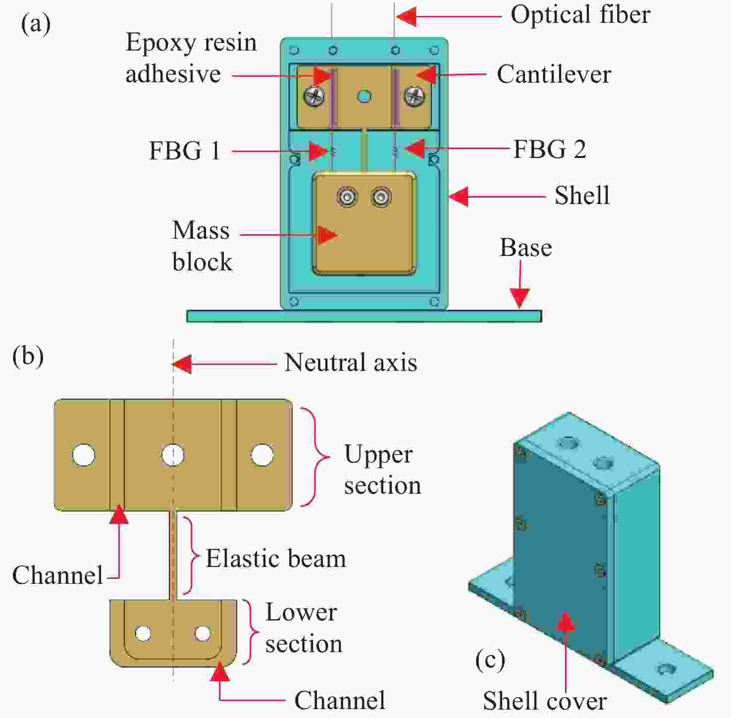
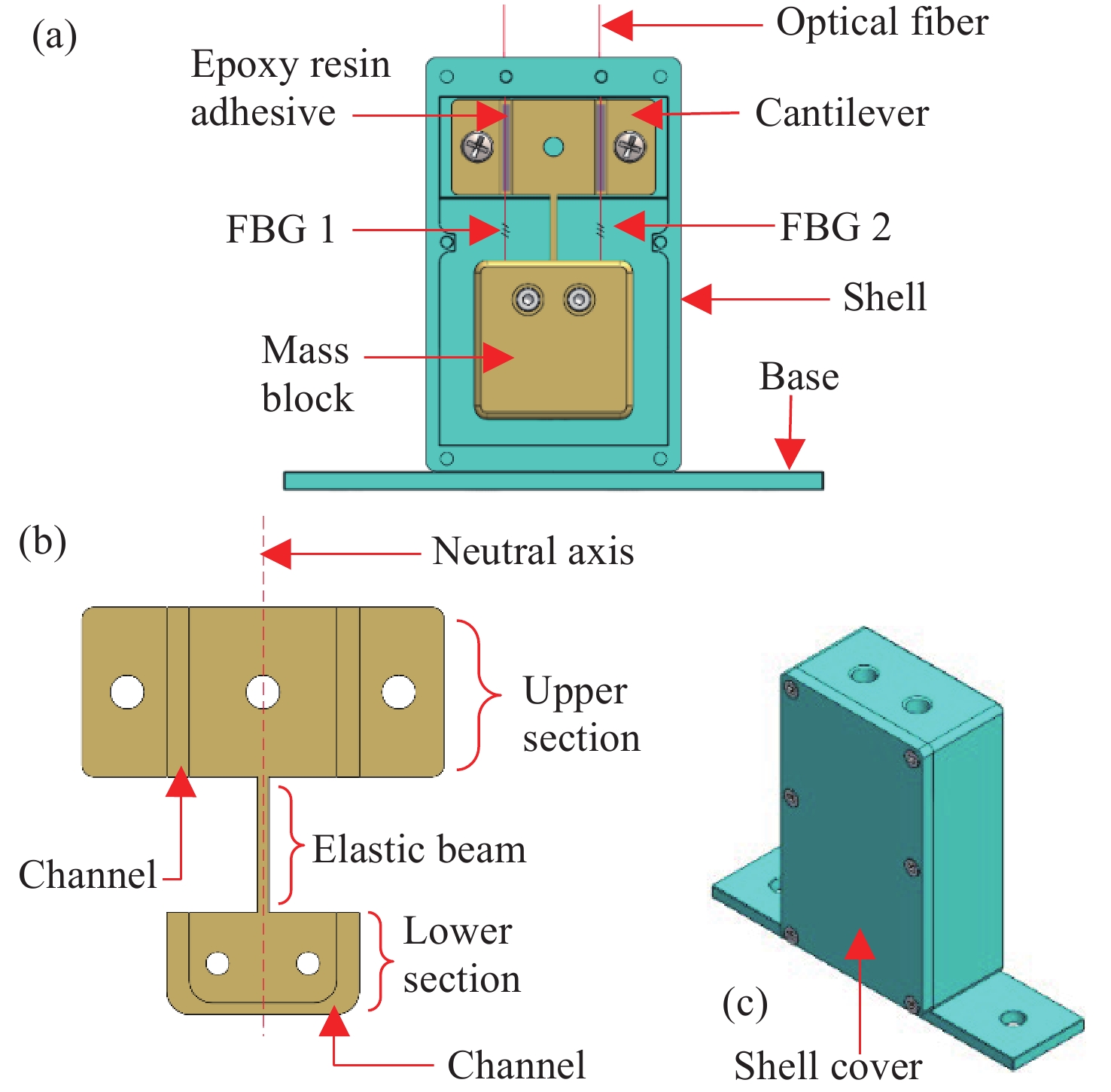
Figure 1. (a) Sensor structure design. (b) Initial cantilever design structure. (c) Sensor assembly
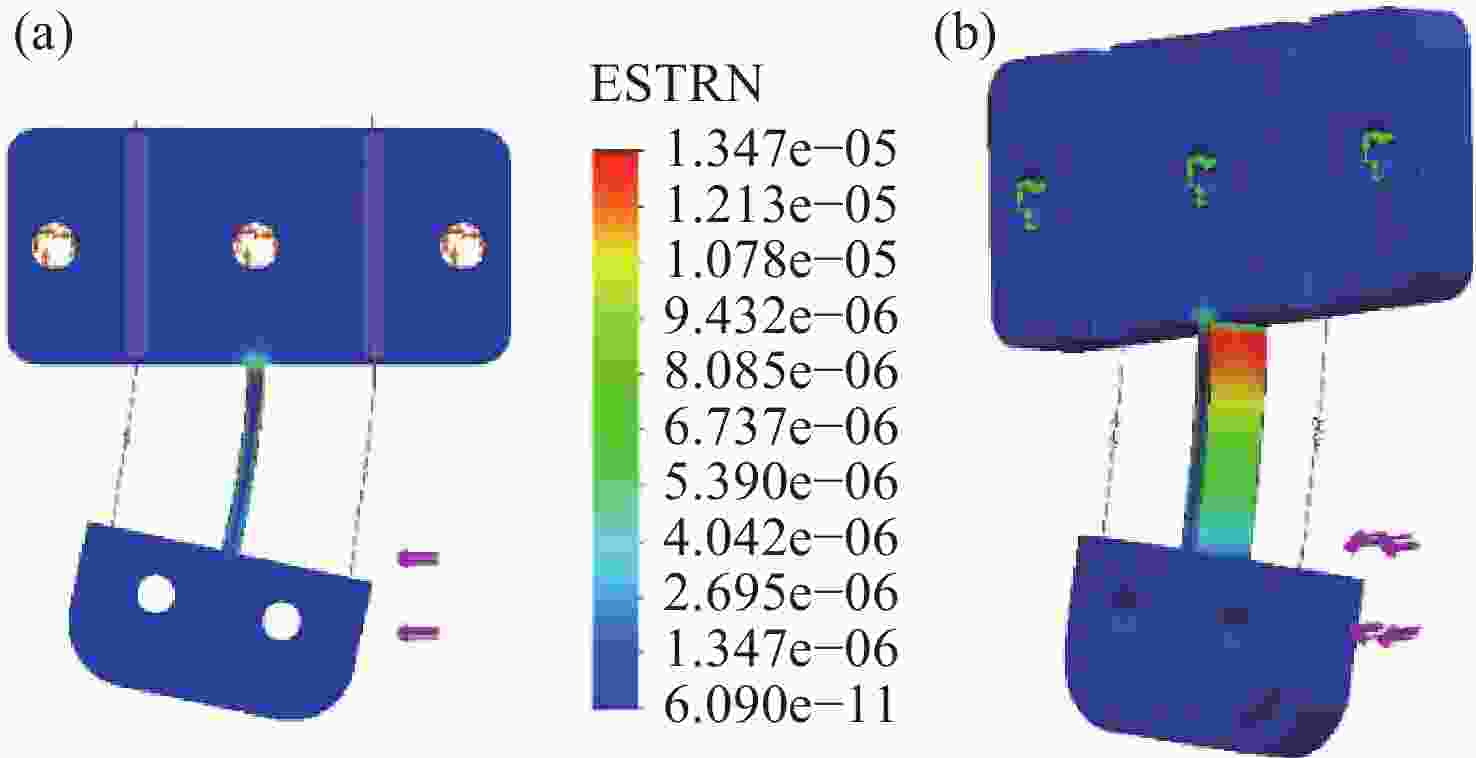
Figure 2. Simulation results of (a) equivalent strain distribution by FEA and (b) the surfaces experiencing maximum strain
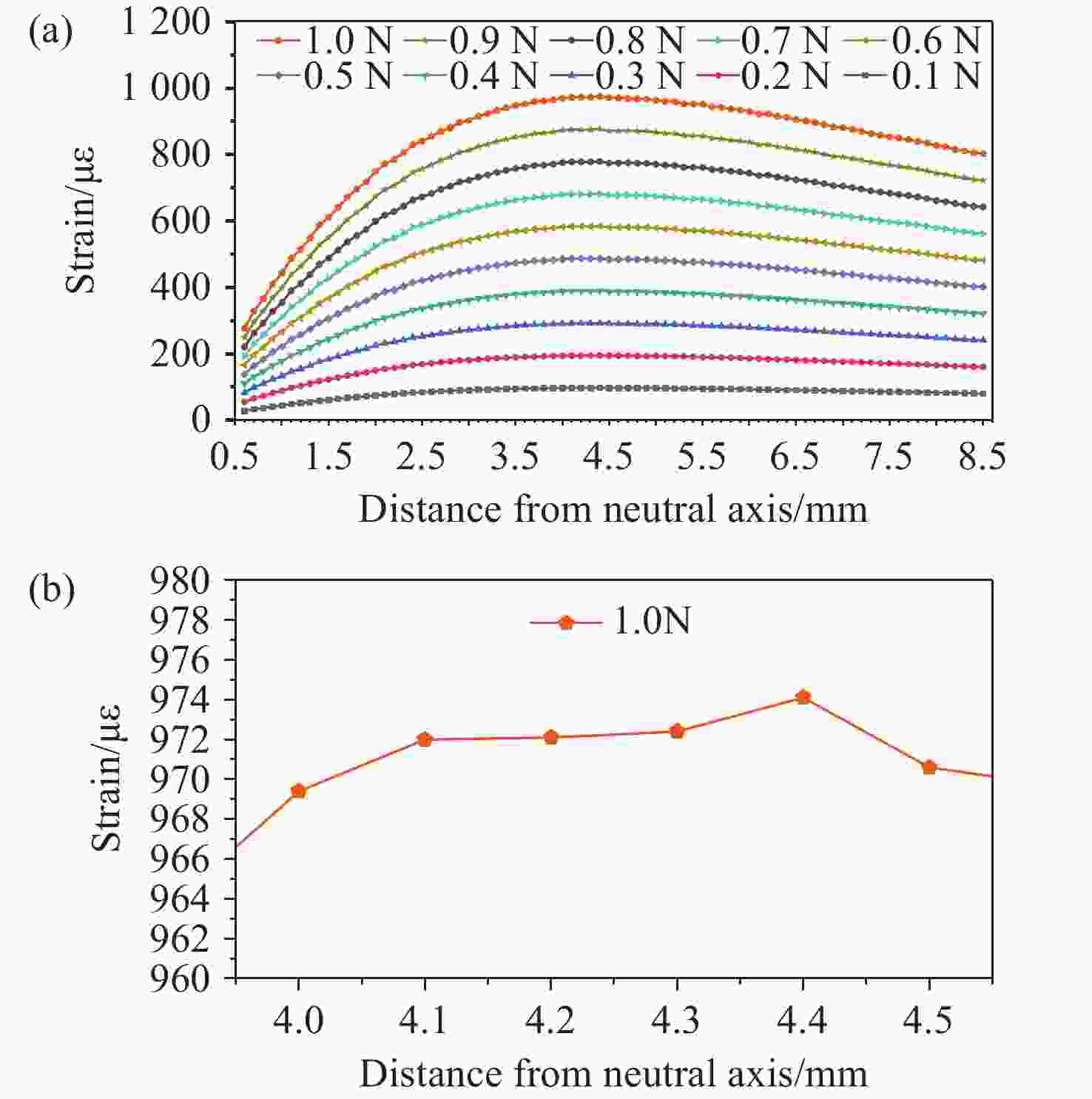
Figure 4. (a) The relation between the position distance from the neutral axis, applied force, and strain. (b) Amplified diagram showing the maximum strain of 1.0 N
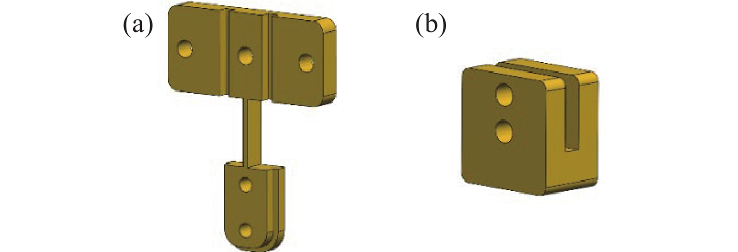
Figure 5. (a) Optimized cantilever structure design and (b) the corresponding mass block design
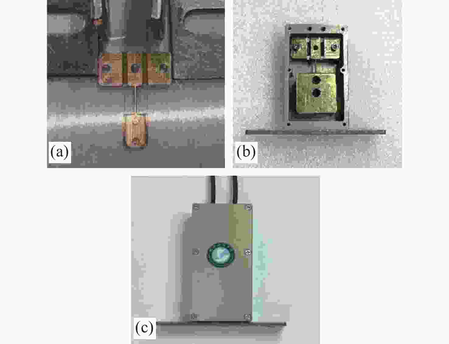
Figure 6. Fabricated prototype of physical sensor. (a) Cantilever with prestressed FBGs. (b) Sensor structure design. (c) Assembled sensor
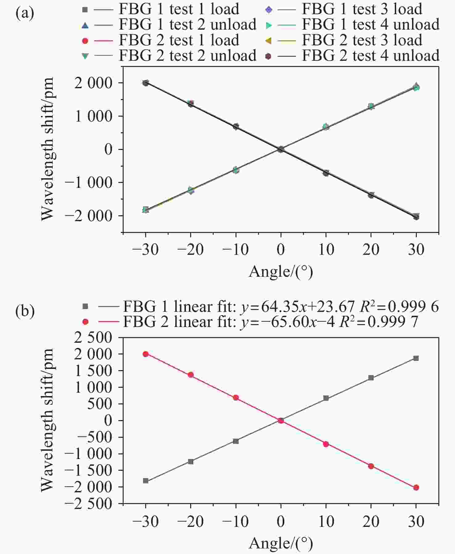
Figure 8. (a)Wavelength shifts of FBG1 and FBG2 for the four tilt tests. (b) Average wavelength shifts responses of FBG1 and FBG2
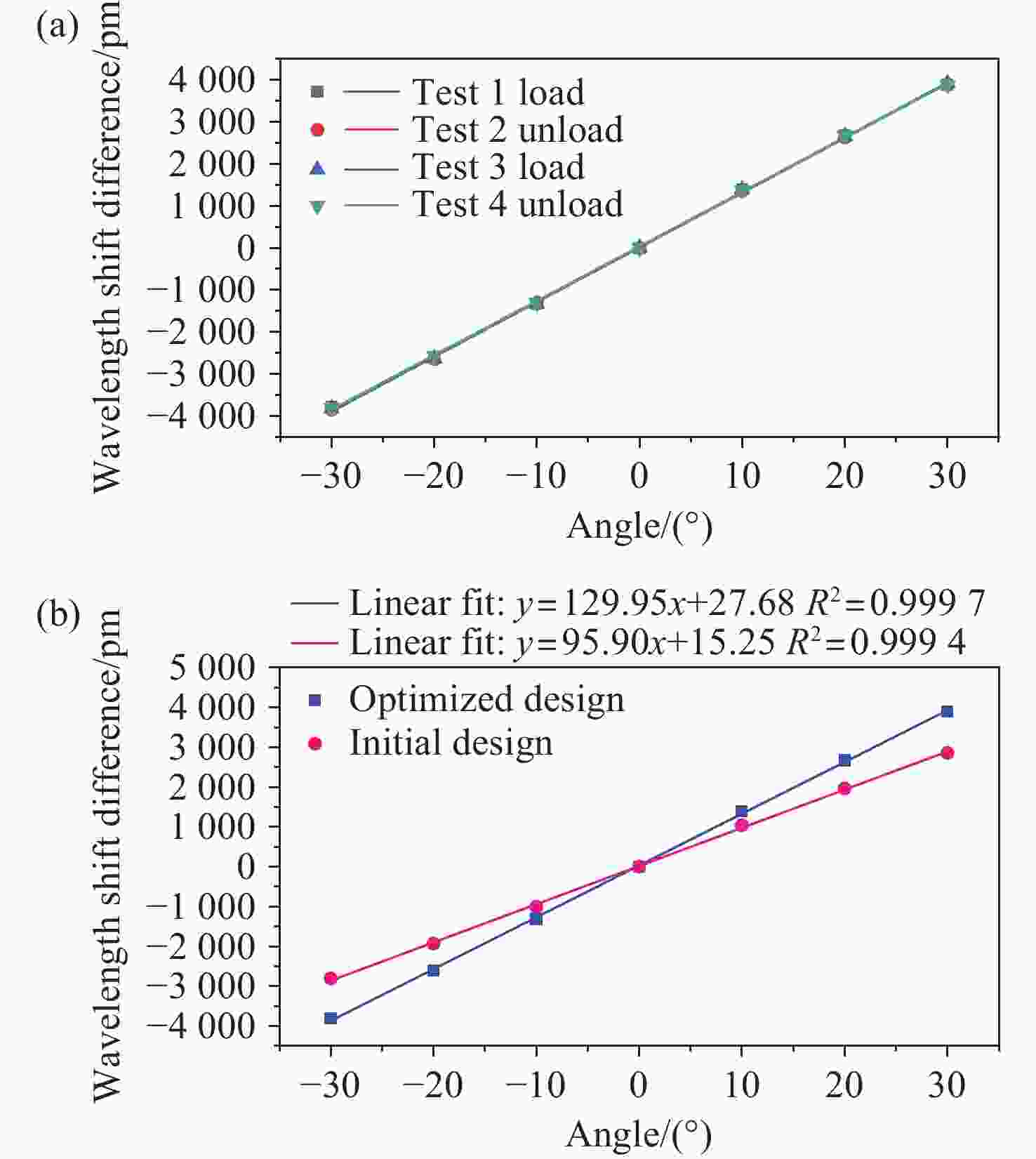
Figure 9. (a) Wavelength shifts difference of FBG1 and FBG2. (b) Linear fit for the average values of the wavelength shift difference of the optimized and initial design
 下载:


