


Domestic 3D visualization diffractive waveguide simulation module based on ray-field tracing
-
摘要:
自主研发了国内首款基于光线场追迹的3D可视化光波导设计仿真模块。应用该仿真模块设计了一款二维出瞳扩展的衍射光波导,展示了从光栅的
k Abstract:This work introduces the first domestically developed 3D visualization module for optical waveguide design and simulation based on ray-field tracing. Using this module, we engineers a two-dimensional exit-pupil-expansion diffractive waveguide, demonstrating a systematic design workflow, which integrates
k -
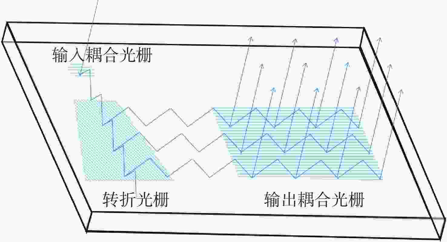
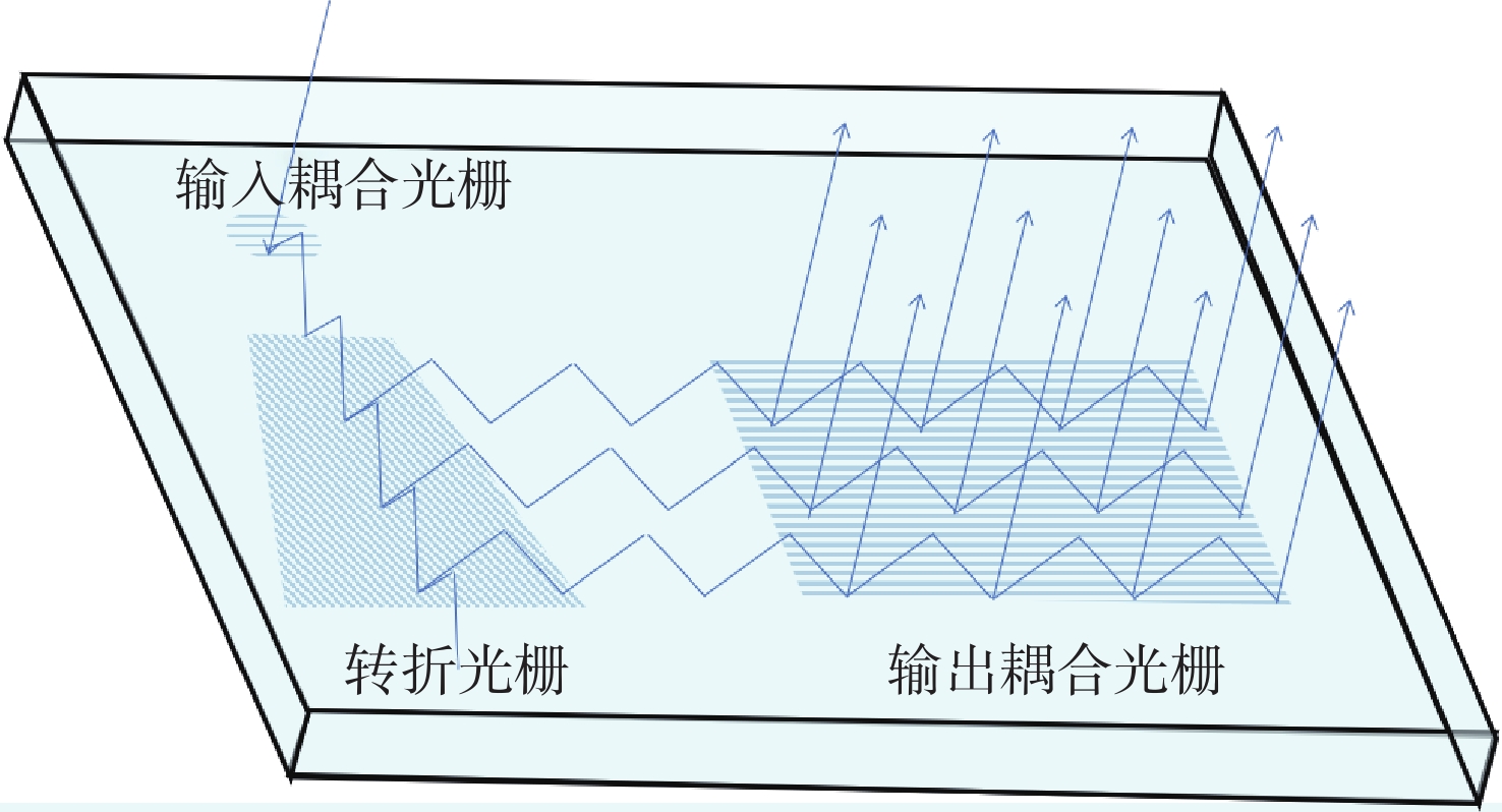
图 1 二维出瞳扩展衍射光波导中的光线传播示意图
Figure 1. Schematic diagram of ray propagation in a 2D exit pupil expansion diffractive waveguide
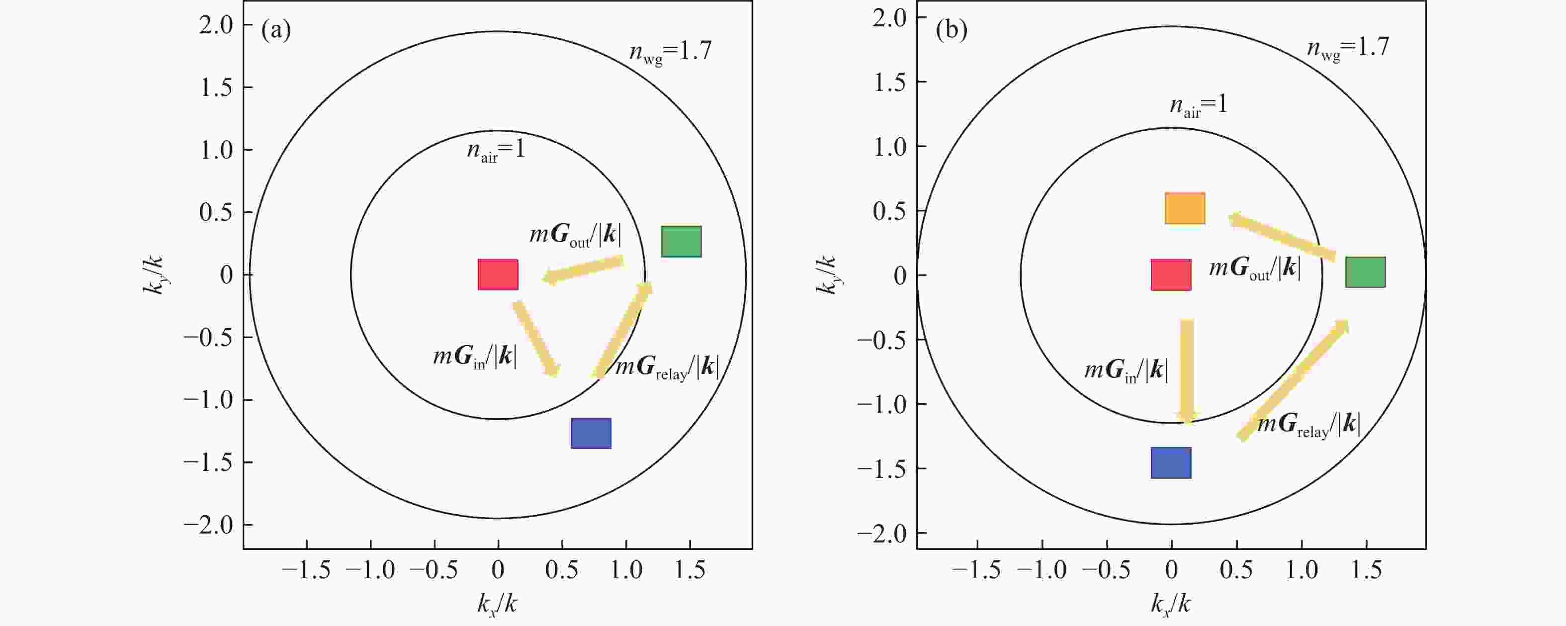
图 2 (a)二维出瞳扩展衍射光波导对应的归一化k矢量图;(b)衍射光波导中的三组光栅不匹配
Figure 2. (a) Corresponding normalized k-vector diagram of the 2D exit pupil expansion diffractive waveguide; (b) mismatch among three sets of gratings in the diffractive optical waveguide
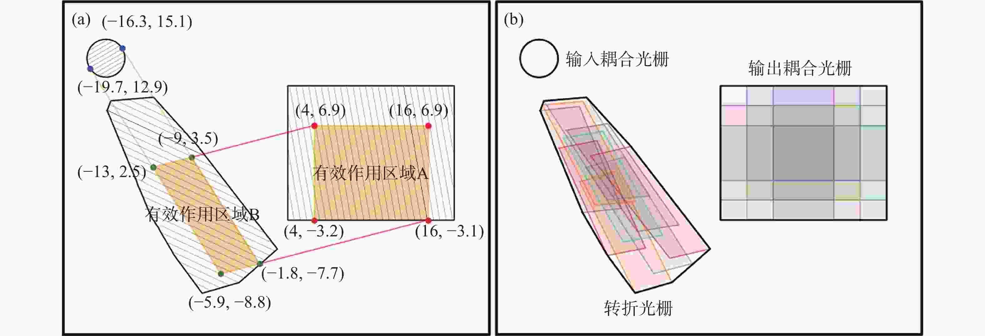
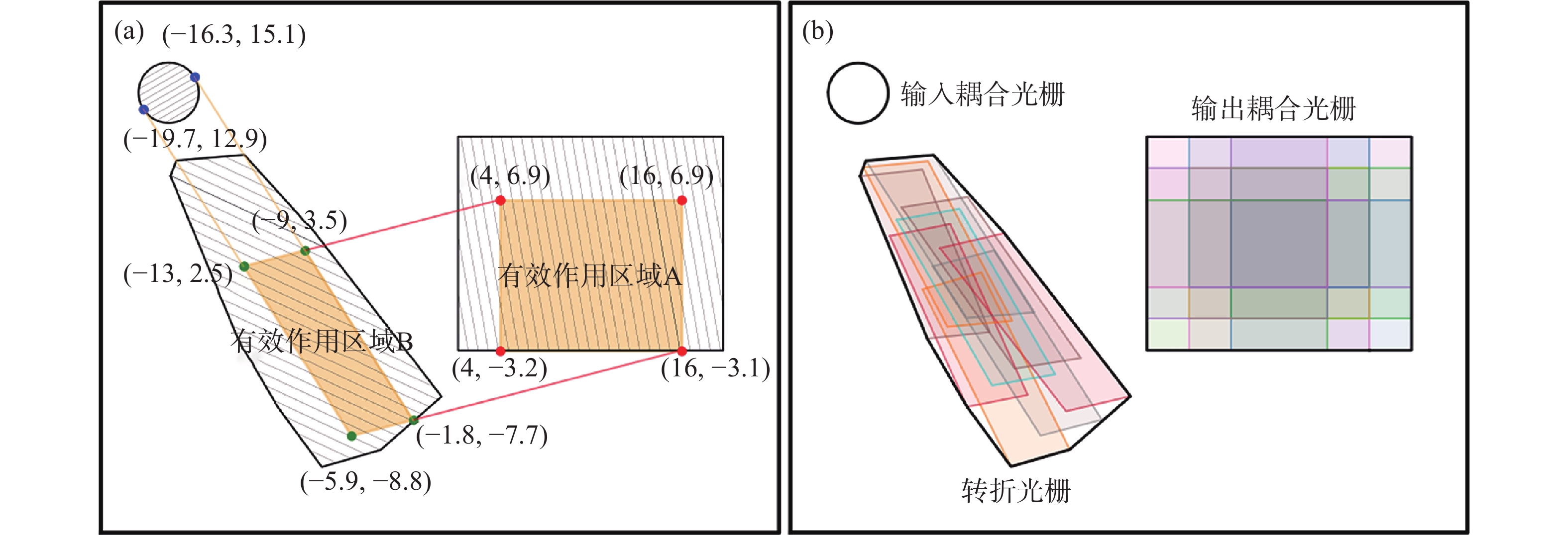
图 3 (a)单一测试视场与转折区域和输出耦合区域的有效作用位置;(b)多个有效作用区域的集合划定转折区域和输出耦合区域
Figure 3. (a) Effective region positions of a single test field of view interacted with the redirection coupling region and output coupling region; (b) the delineation of the redirection coupling region and output coupling region by the aggregation of multiple effective interaction regions
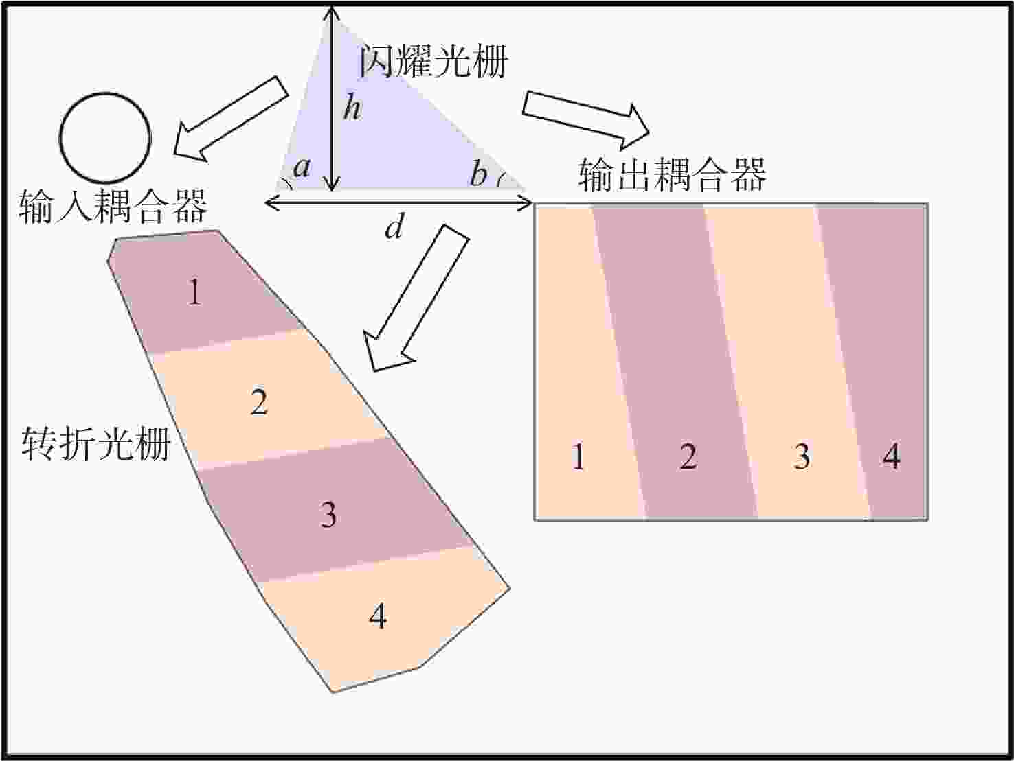
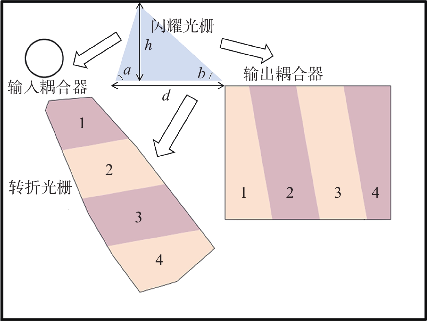
图 4 衍射光波导的分区示意图
Figure 4. Schematic diagram of the partitioning of diffractive optical waveguide
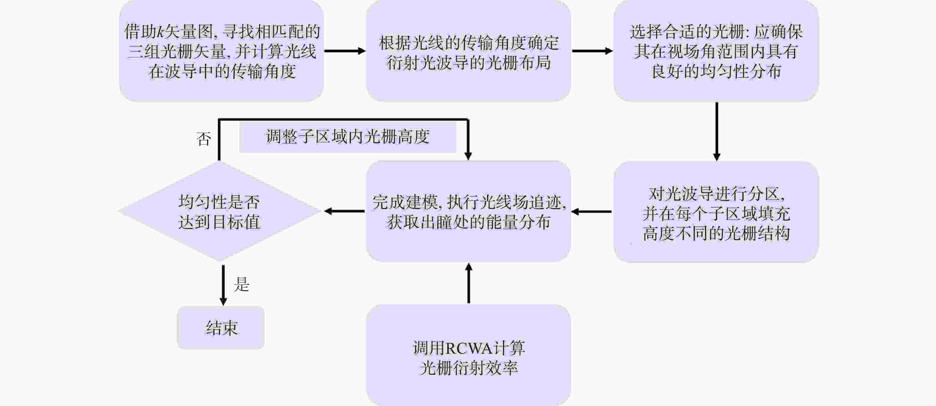
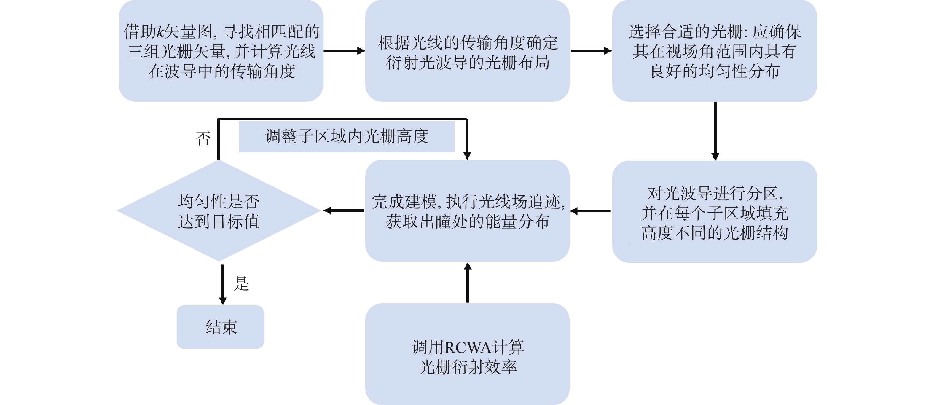
图 5 衍射光波导设计优化流程图
Figure 5. Flowchart of the design and optimization process for the diffractive optical waveguide
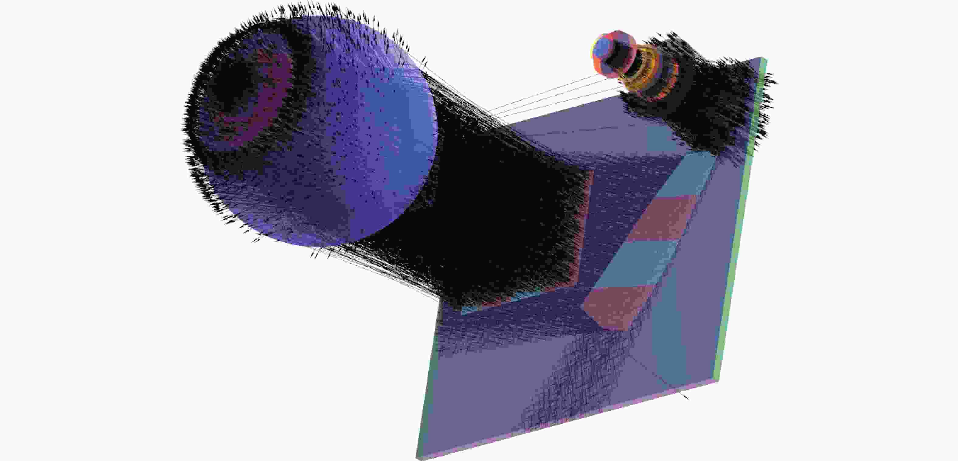
图 6 可视化3D衍射光波导模组示意图
Figure 6. Schematic diagram of the 3D visualization diffractive waveguide module
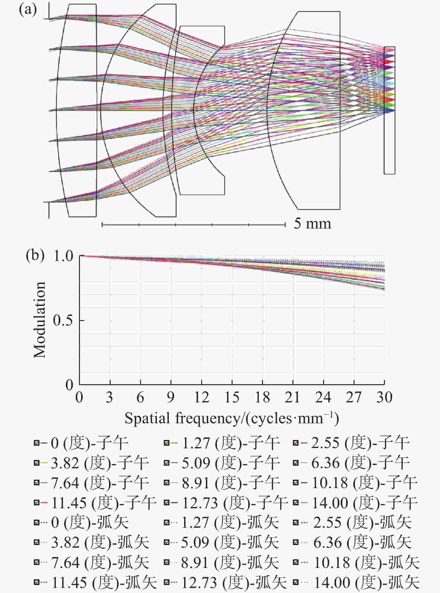
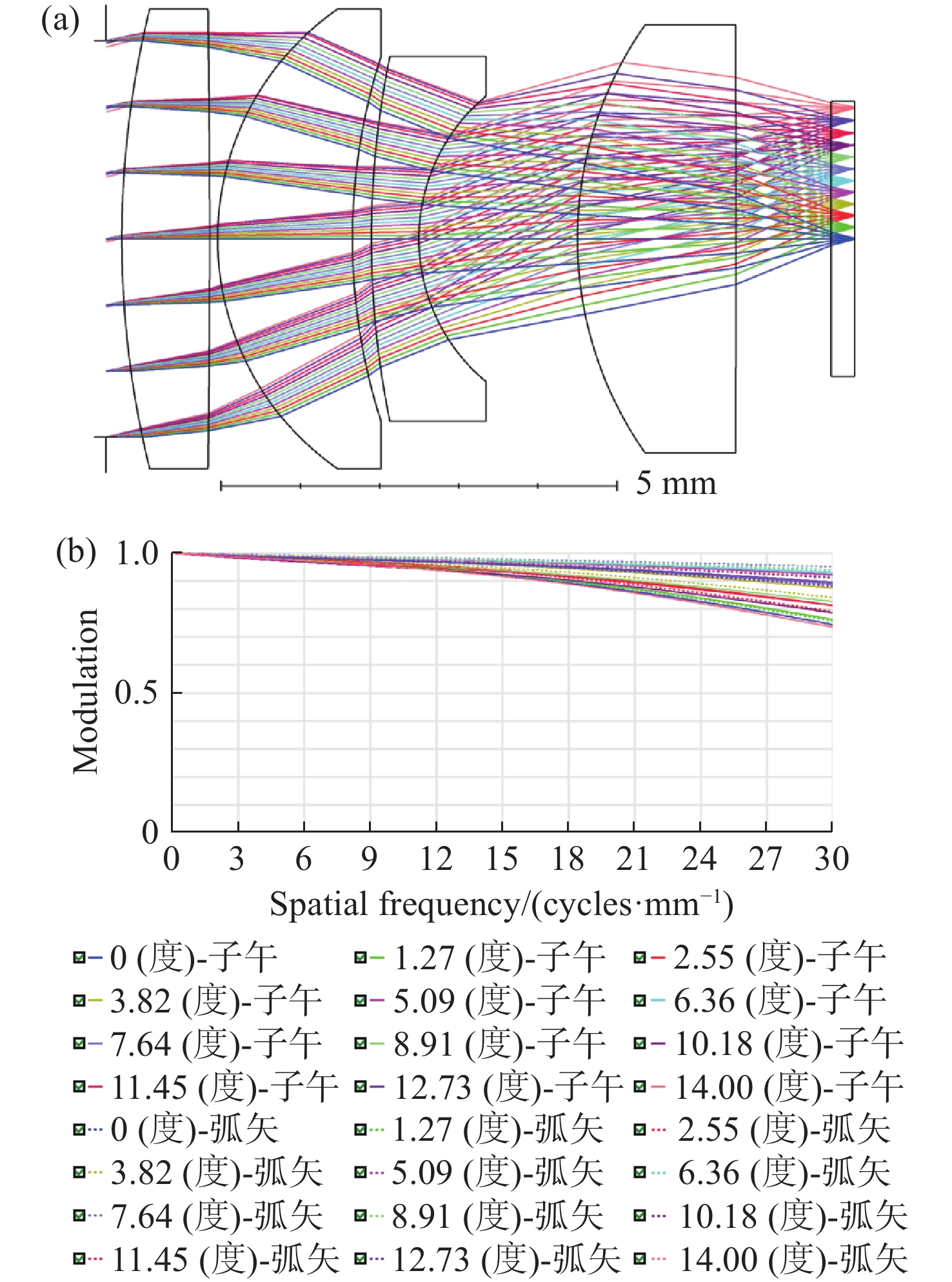
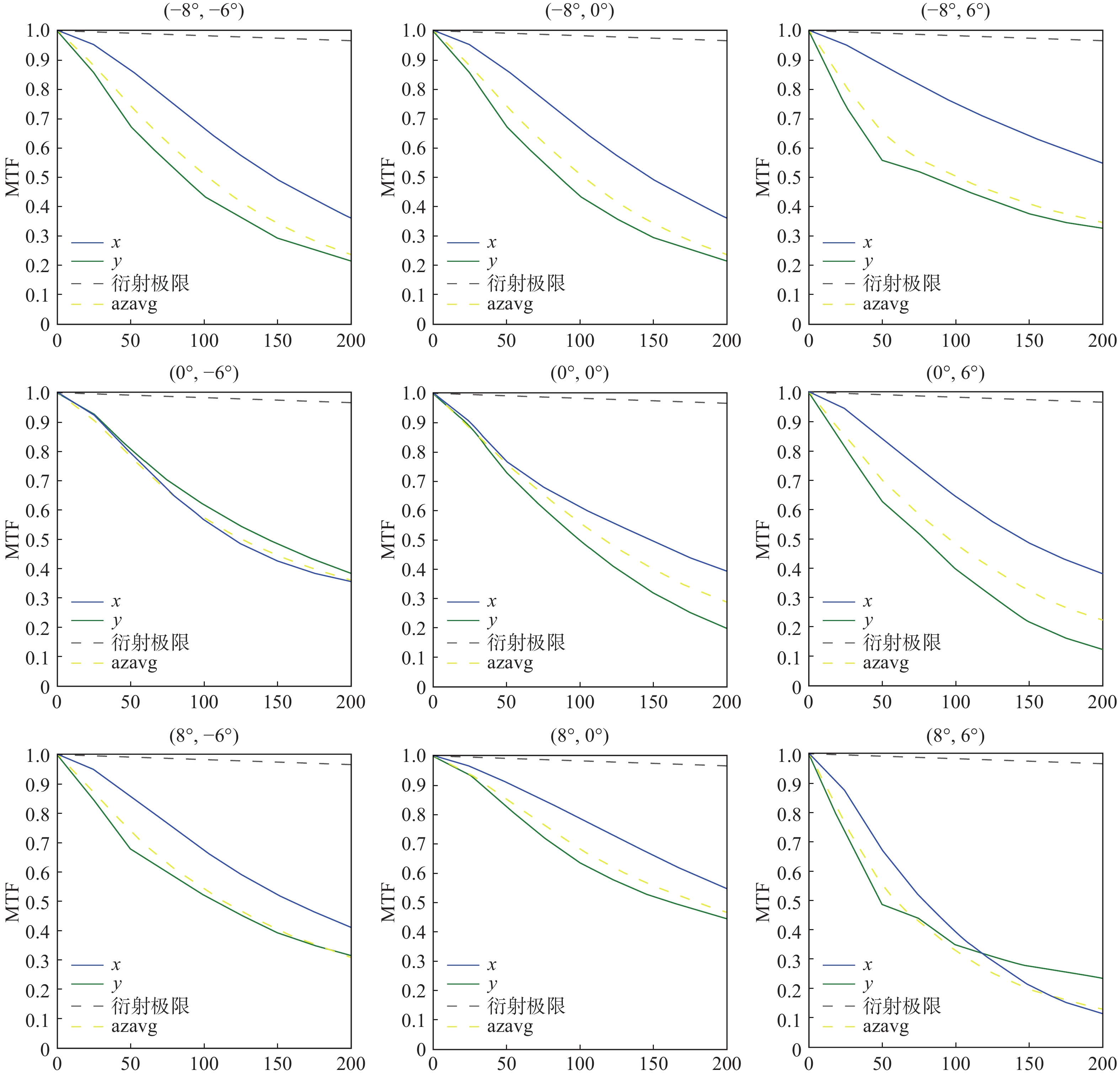
图 7 (a)投影光学系统布局;(b)投影光学系统的MTF
Figure 7. (a) Optical layout of the projection optics system; (b) MTF of the projection optics system
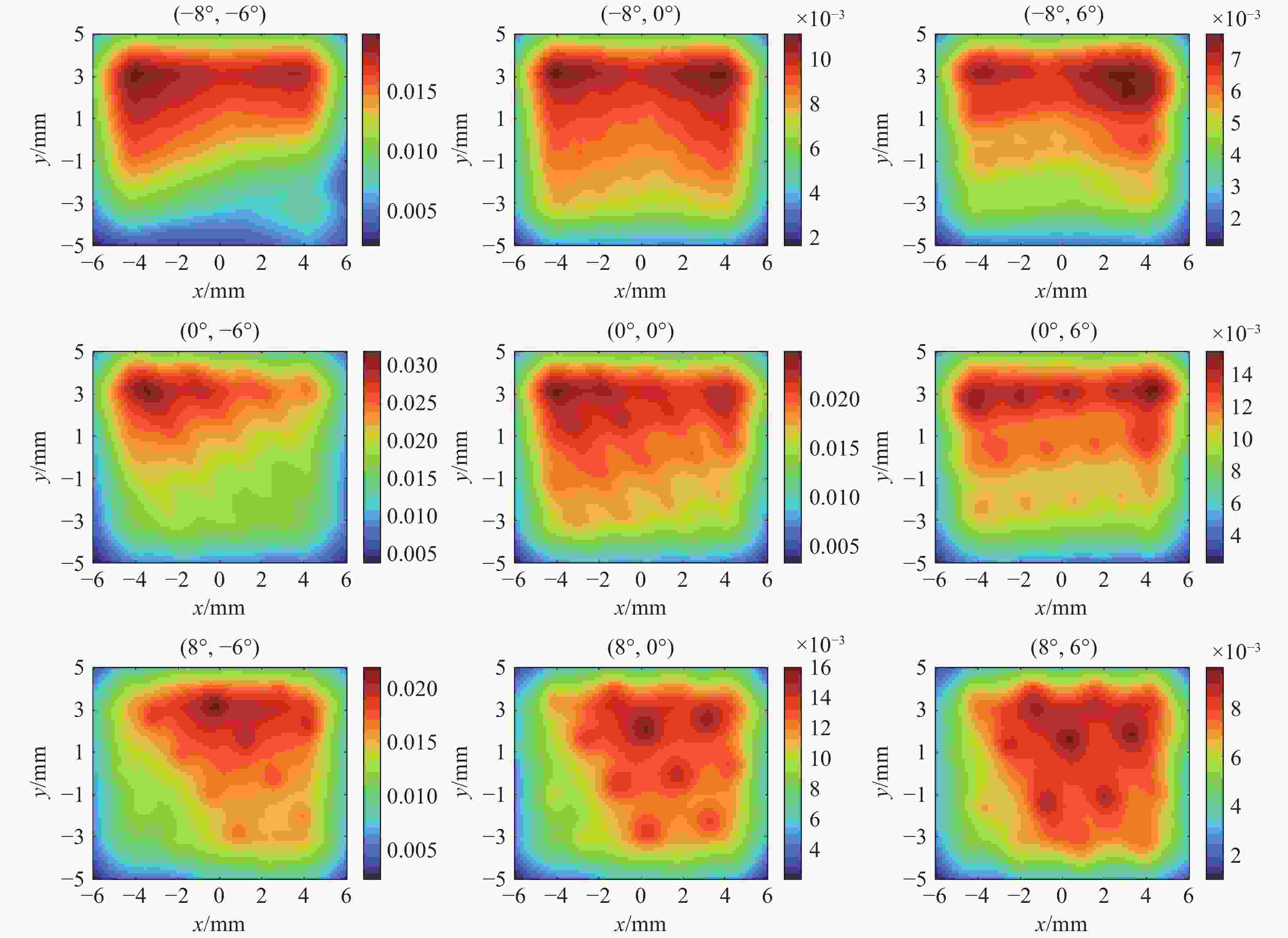
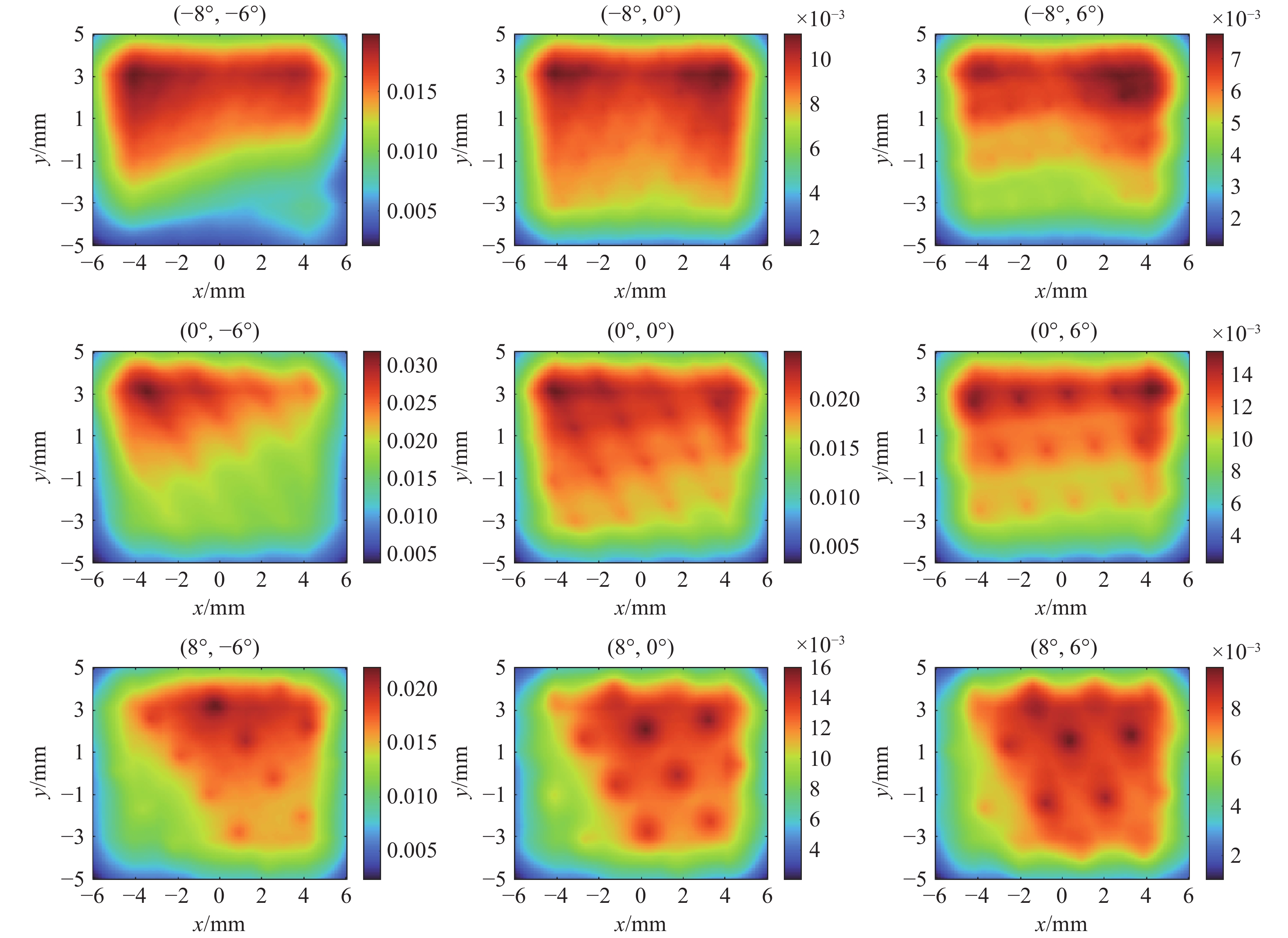
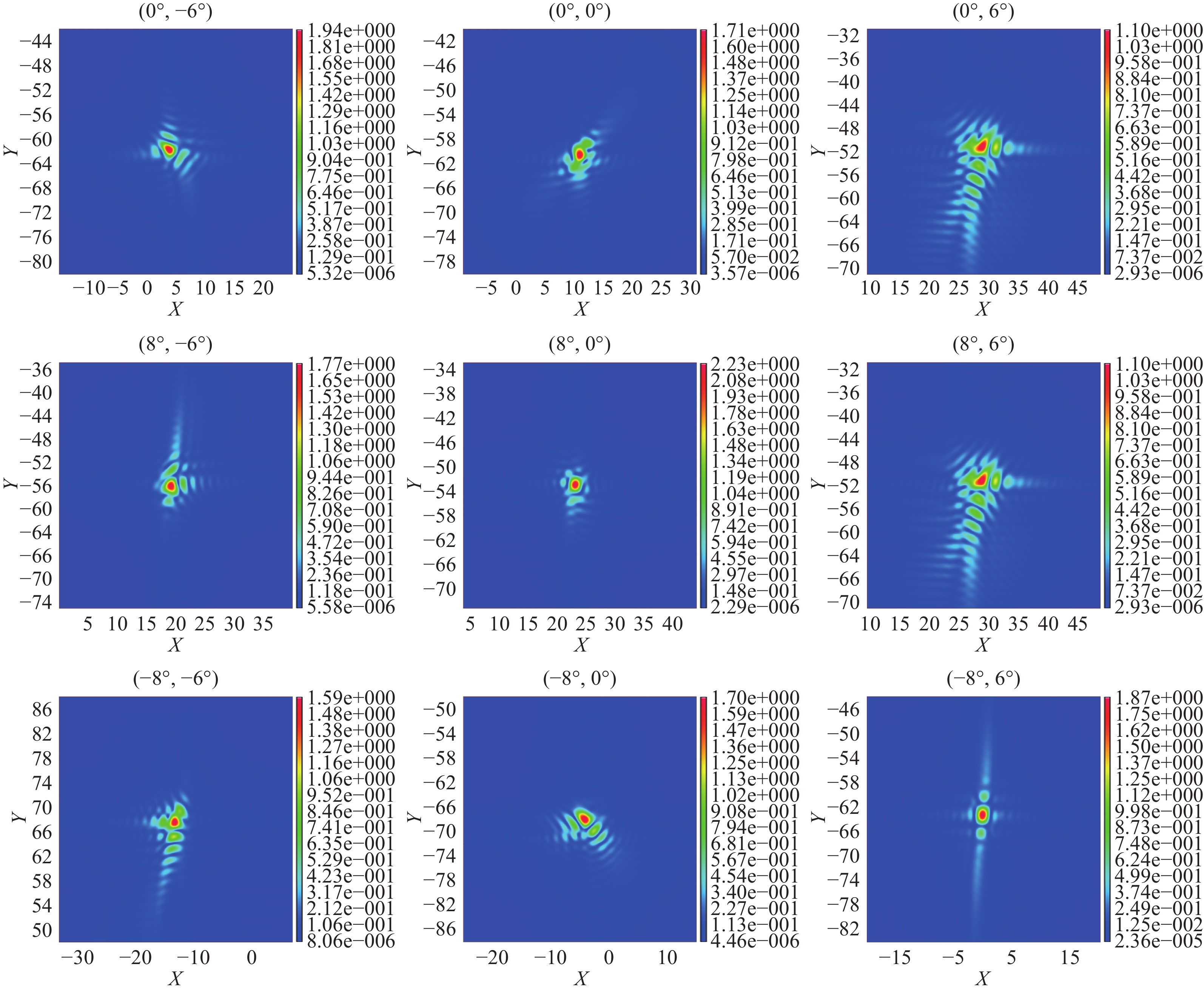
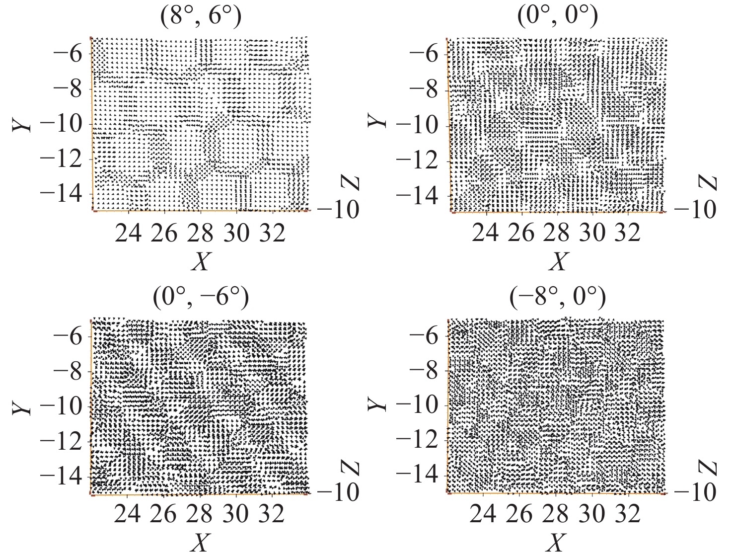
图 8 9个视场角在出瞳处的辐照度分布
Figure 8. Irradiance distribution at the exit pupil for nine fields of view
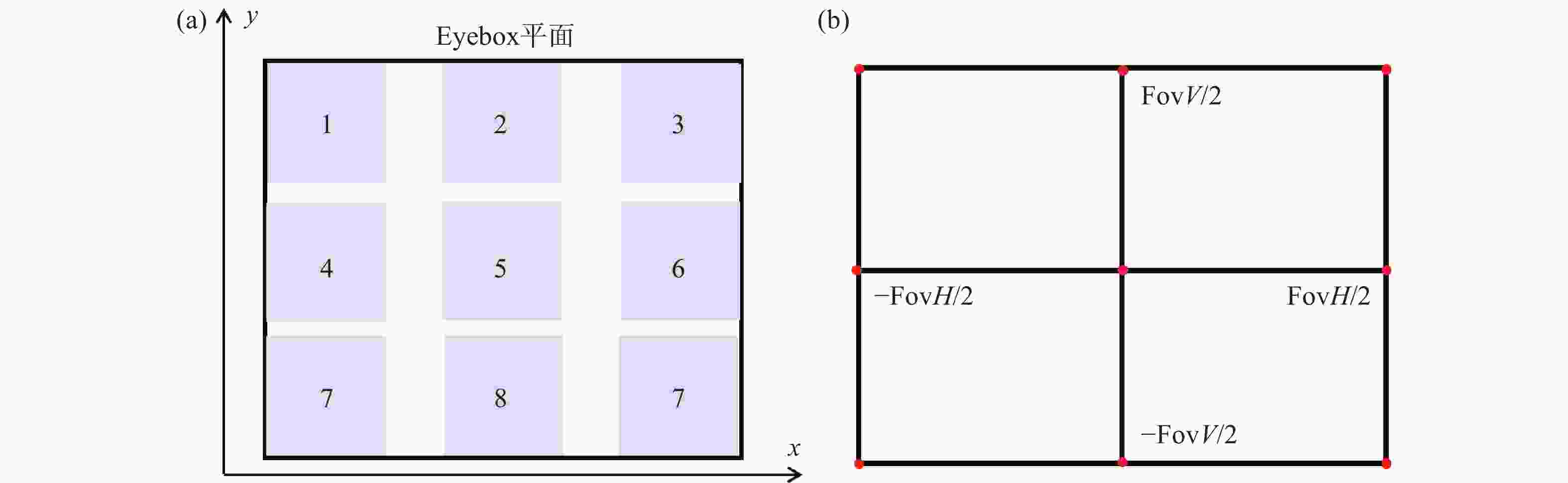
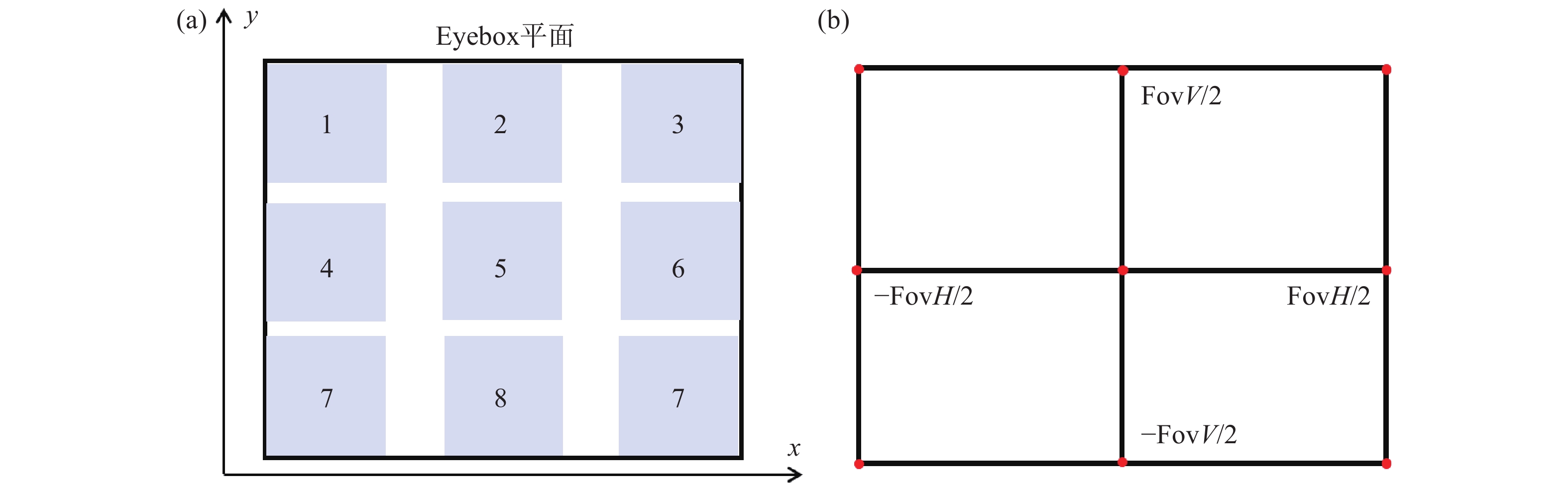
图 9 9个子区域的取样方法。(a)在eyebox平面选取不同的出瞳区域;(b)选择不同的测试视场角
Figure 9. Sampling method for nine sub-regions. (a) Selection of different exit pupil regions on the eyebox plane; (b) selection of different test fields of view
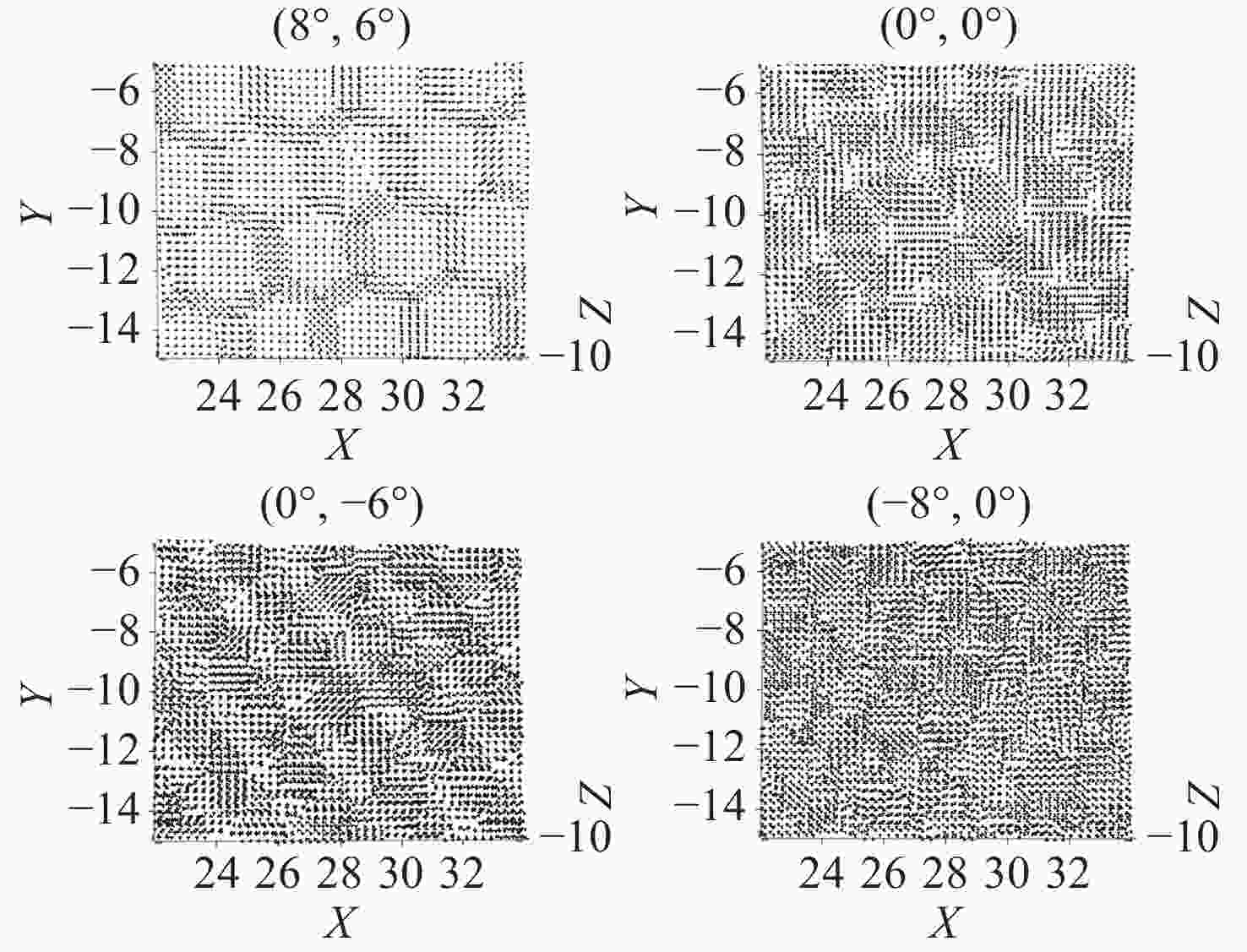
图 12 特定的偏振光入射时可以查看在眼动范围平面处的光的偏振态
Figure 12. The polarization state of light can be observed at the eyebox when a specific polarized light is incident
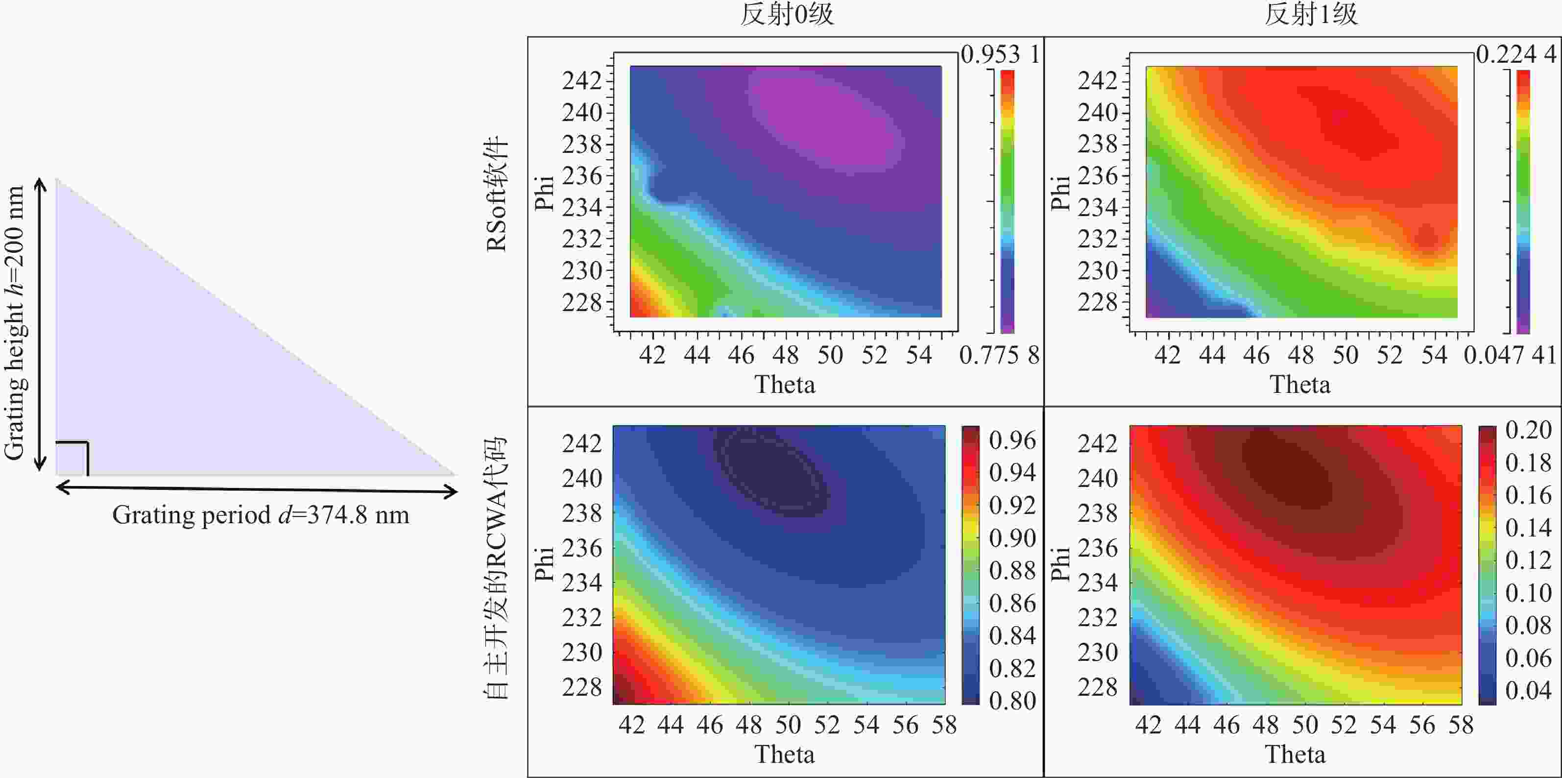
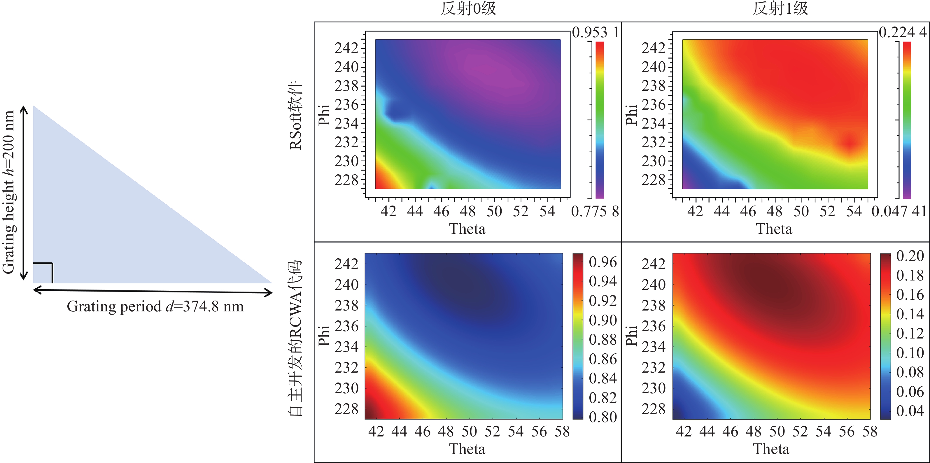
图 13 Rsoft和自主开发的光栅计算模块效率对比
Figure 13. Efficiency comparison between Rsoft and the self-developed diffraction calculation module
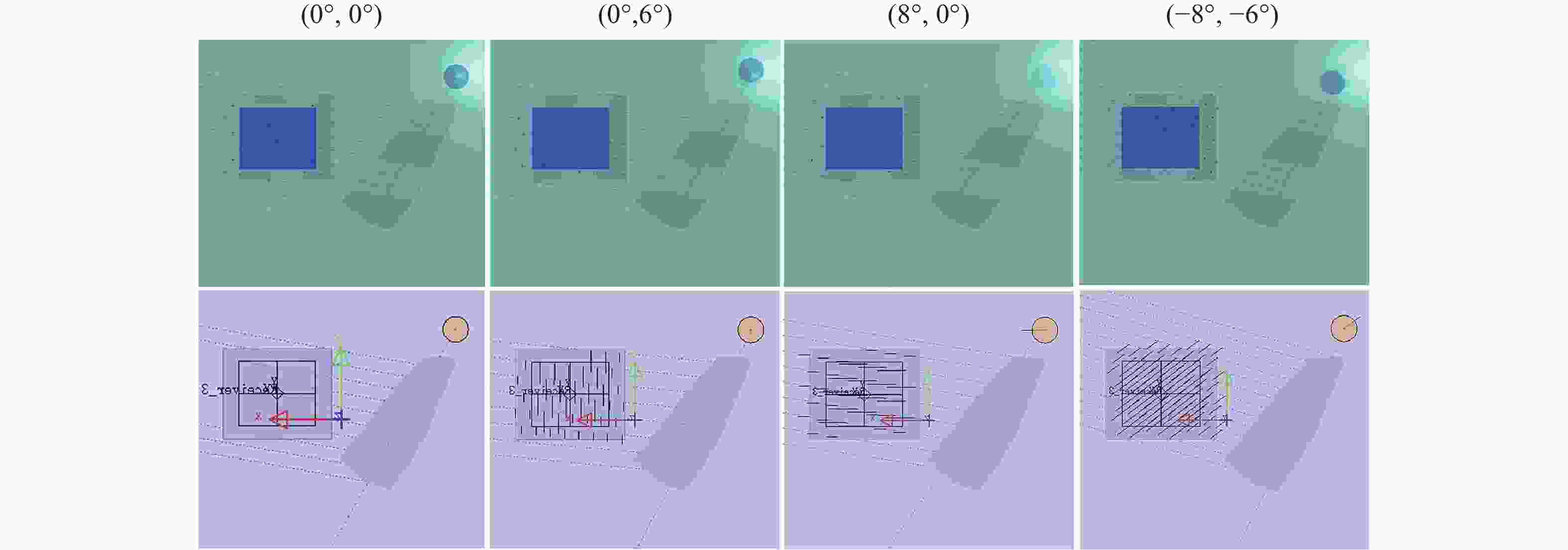
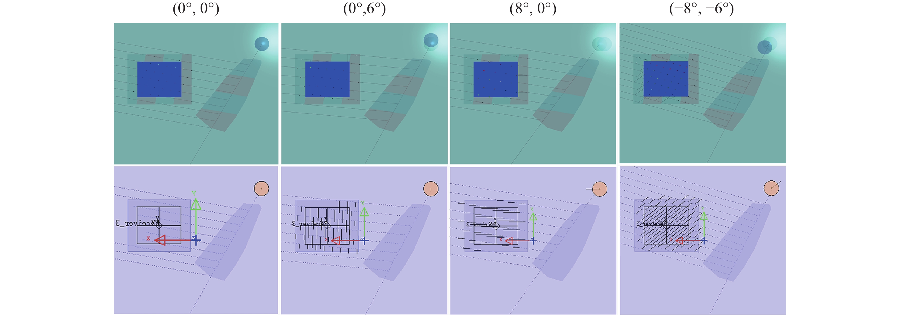
图 14 自主光波导模块与LightTools的光线路径对比
Figure 14. Comparison of ray paths between the self-developed optical waveguide module and LightTools
表 1 输入光的k矢量和角度信息
Table 1. k-vector and angular information of the incident light
θH/(°) θV/(°) kinx/|kin| kiny/|kin| θin/(°) φin/(°) 输入光 −8 −6 − 0.1375 0.1032 9.9 143.1 −8 0 − 0.1383 0 7.95 180 −8 6 − 0.1375 − 0.1032 9.9 216.9 0 −6 0 0.1042 5.98 90 0 0 0 0 0 0 0 6 0 − 0.1042 5.98 270 8 −6 0.1375 0.1032 9.9 36.9 8 0 0.1383 0 7.95 0 8 6 0.1375 − 0.1032 9.9 323.1  下载: 导出CSV
表 2 输入耦合器偏转后光线的k矢量和角度信息
Table 2. k-vector and angular information of the light rays after deflection by the input grating coupler
kg1x/|kg1| kg1y/|kg1| θg1/(°) φg1/(°) 输入耦合光栅
θG=90°
φG=300°0.502 − 1.0045 41.34 296.55 0.5013 − 1.1077 45.66 294.35 0.502 − 1.2109 50.45 292.52 0.6395 − 1.0036 44.43 302.51 0.6395 − 1.1077 48.8 300 0.6395 − 1.2119 53.71 297.82 0.7771 − 1.0045 48.34 307.72 0.7778 − 1.1077 52.77 305.08 0.7771 − 1.2109 57.82 302.69
下载: 导出CSV
表 3 转折光线偏转后光线的k矢量和角度信息
Table 3. k-vector and angular information of the light rays after deflection by the redirection grating coupler
kg2x/|kg2| kg2y/|kg2| θg2/(°) φg2/(°) 转折光栅
θG=90°
φG=65°1.1221 0.3253 43.41 16.17 1.1214 0.2221 42.26 11.2 1.1221 0.1189 41.59 6.05 1.2596 0.3263 49.94 14.52 1.2596 0.2221 48.8 10 1.2596 0.118 48.09 5.35 1.3972 0.3253 57.55 13.11 1.3979 0.2221 56.37 9.03 1.3972 0.1189 55.57 4.87
下载: 导出CSV
表 4 输出耦合器偏转后光线的k矢量和角度信息
Table 4. k-vector and angular information of the light rays after deflection by the output grating coupler
koutx/|kout| kouty/|kout| θout/(°) φout/(°) 输出耦合光栅
θG=90°
φG=180°− 0.1375 0.1032 9.9 143.13 − 0.1383 0 7.95 180 − 0.1375 − 0.1032 9.9 216.87 0 0.1042 5.98 90 0 0 0 0 0 − 0.1042 5.98 270 0.1375 0.1032 9.9 36.87 0.1383 0 7.95 0 0.1375 − 0.1032 9.9 323.13
下载: 导出CSV
表 5 输出耦合区域的边界坐标点
Table 5. Boundary coordinate points of the output coupling region
x/mm y/mm 输出耦合区域 18.79 11.10 18.79 −3.10 1.21 −3.10 1.21 11.10
下载: 导出CSV
表 6 转折区域的边界坐标点
Table 6. Boundary coordinate points of the redirection coupling region
x/mm y/mm 转折区域 −17.876 8.479813 − 13.3992 − 2.31754 − 10.7563 − 6.85092 − 7.83561 − 10.8154 − 3.93101 − 9.68321 0.108358 − 6.14503 − 8.27717 4.69675 −12.983 9.885263 − 17.4894 9.501308 − 17.6559 9.067004
下载: 导出CSV
表 7 衍射光波导中3个耦合光栅及其子区域的光栅参数
Table 7. Grating parameters of the three coupling gratings and their subregions in the diffractive optical waveguide
波导区域 光栅类型 高度/μm a/(°) b/(°) 输入耦合光栅 闪耀光栅 0.15 34.902 34.902 转折光栅—子区域1 0.08 90 12.05 转折光栅—子区域2 0.08 90 12.05 转折光栅—子区域3 0.07 90 10.58 转折光栅—子区域4 0.11 90 16.36 输出耦合光栅—子区域1 0.08 34.82 14.25 输出耦合光栅—子区域2 0.1 41.009 17.613 输出耦合光栅—子区域3 0.12 46.219 20.85 输出耦合光栅—子区域4 0.11 43.73 19.25
下载: 导出CSV
表 8 各区域亮度值及均匀度分布
Table 8. Luminance value and uniformity distribution of each region
视场角(°) 能量 I1 I2 I3 I4 I5 I6 I7 I8 I9 出瞳均匀性(%) (−8, −6) 5.7E-06 4.2E-06 2.5E-06 9.2E-06 9.0E-06 5.6E-06 6.1E-06 4.7E-06 2.9E-06 43.36 (−8, 0) 4.3E-06 3.9E-06 2.4E-06 9.7E-06 8.9E-06 5.1E-06 7.8E-06 6.7E-06 3.9E-06 40.04 (−8, 6) 4.6E-06 4.0E-06 2.7E-06 9.1E-06 8.5E-06 5.2E-06 8.3E-06 6.1E-06 4.0E-06 45.61 (0, −6) 8.8E-06 4.9E-06 3.0E-06 1.2E-05 1.1E-05 6.6E-06 7.2E-06 5.1E-06 3.2E-06 40.83 (0, 0) 7.5E-06 4.6E-06 3.0E-06 1.1E-05 1.1E-05 6.3E-06 9.0E-06 7.2E-06 4.4E-06 42.27 (0, 6) 6.8E-06 5.0E-06 3.5E-06 1.0E-05 1.0E-05 6.6E-06 8.7E-06 6.9E-06 4.1E-06 50.11 (8, −6) 1.1E-05 5.9E-06 3.9E-06 1.6E-05 1.3E-05 7.9E-06 8.8E-06 6.2E-06 3.8E-06 39.06 (8, 0) 9.4E-06 5.5E-06 3.8E-06 1.5E-05 1.2E-05 7.7E-06 1.1E-05 7.7E-06 4.6E-06 40.87 (8, 6) 9.8E-06 5.9E-06 4.1E-06 1.3E-05 1.3E-05 8.4E-06 1.0E-05 7.5E-06 4.5E-06 47.41 视场均匀性(%) 57.54 79.15 74.94 73.04 79.08 75.18 70.36 76.03 78.12
下载: 导出CSV
-
[1] 史晓刚, 薛正辉, 李会会, 等. 增强现实显示技术综述[J]. 中国光学,2021,14(5):1146-1161. doi: 10.37188/CO.2021-0032SHI X G, XUE ZH H, LI H H, et al. Review of augmented reality display technology[J]. Chinese Optics, 2021, 14(5): 1146-1161. (in Chinese). doi: 10.37188/CO.2021-0032 [2] DING Y Q, YANG Q, LI Y N Q, et al. Waveguide-based augmented reality displays: perspectives and challenges[J]. eLight, 2023, 3(1): 24. doi: 10.1186/s43593-023-00057-z [3] ROLLAND J P, GOODSELL J. Waveguide-based augmented reality displays: a highlight[J]. Light: Science & Applications, 2024, 13(1): 22. [4] LU Y Q, LI Y. Planar liquid crystal polarization optics for near-eye displays[J]. Light: Science & Applications, 2021, 10(1): 122. [5] SONG W T, LIANG X N, LI SH Q, et al. Retinal projection near‐eye displays with Huygens’ metasurfaces[J]. Advanced Optical Materials, 2023, 11(5): 2202348. doi: 10.1002/adom.202202348 [6] PARK J H, LEE B. Holographic techniques for augmented reality and virtual reality near-eye displays[J]. Light: Advanced Manufacturing, 2022, 3(1): 137-150. [7] CHENG D W, DUAN J X, CHEN H L, et al. Freeform OST-HMD system with large exit pupil diameter and vision correction capability[J]. Photonics Research, 2022, 10(1): 21-32. doi: 10.1364/PRJ.440018 [8] CHENG D W, WANG Q W, LIU Y, et al. Design and manufacture AR head-mounted displays: a review and outlook[J]. Light: Advanced Manufacturing, 2021, 2(3): 350-369. [9] JANG C W, BANG K, CHAE M, et al. Waveguide holography for 3D augmented reality glasses[J]. Nature Communications, 2024, 15(1): 66. doi: 10.1038/s41467-023-44032-1 [10] DING Y Q, LI Y N Q, YANG Q, et al. Design optimization of polarization volume gratings for full-color waveguide-based augmented reality displays[J]. Journal of the Society for Information Display, 2023, 31(5): 380-386. doi: 10.1002/jsid.1206 [11] XIONG J H, WU S T. Planar liquid crystal polarization optics for augmented reality and virtual reality: from fundamentals to applications[J]. eLight, 2021, 1: 3. doi: 10.1186/s43593-021-00003-x [12] LI ZH, LUO X H, WANG J, et al. Phase space framework enables a variable-scale diffraction model for coherent imaging and display[J]. Photonics Research, 2024, 12(9): 1937. doi: 10.1364/PRJ.523568 [13] WENG X Y, SONG Q, LI X M, et al. Free-space creation of ultralong anti-diffracting beam with multiple energy oscillations adjusted using optical pen[J]. Nature Communications, 2018, 9(1): 5035. doi: 10.1038/s41467-018-07282-y [14] CHENG H H, CHEN Y, CHRISTOPHE A, et al. Optimization and tolerance for an exit pupil expander with 2D grating as out-coupler[C]. Proceedings of SPIE 12449, Optical Architectures for Displays and Sensing in Augmented, Virtual, and Mixed Reality (AR, VR, MR) IV, SPIE, 2023: 124490X. [15] YAN SH F, ZHANG E Q, GUO J D, et al. Eyebox uniformity optimization over the full field of view for optical waveguide displays based on linked list processing[J]. Optics Express, 2022, 30(21): 38139-38151. doi: 10.1364/OE.472089 [16] NI D W, CHENG D W, LIU Y, et al. Uniformity improvement of two-dimensional surface relief grating waveguide display using particle swarm optimization[J]. Optics Express, 2022, 30(14): 24523-24543. doi: 10.1364/OE.462384 [17] LI Z Y, GAO CH, LI H F, et al. Angular uniformity improvement of diffractive waveguide display based on region geometry optimization[J]. Applied Optics, 2024, 63(10): 2494-2502. doi: 10.1364/AO.515428 [18] LEVOLA T. Diffractive optics for virtual reality displays[J]. Journal of the Society for Information Display, 2006, 14(5): 467-475. doi: 10.1889/1.2206112 [19] KONG D Q, ZHAO ZH, SHI X G, et al. Optimization of gratings in a diffractive waveguide using relative-direction-cosine diagrams[J]. Optics Express, 2021, 29(22): 36720-36733. doi: 10.1364/OE.433515 [20] 李俊昌. 衍射计算及数字全息[M]. 北京: 科学出版社, 2014.LI J CH. Diffration Calculation and Digital Holography[M]. Beijing: Science Press, 2014. (in Chinese) [21] GOODMAN J W. Introduction to Fourier Optics[M]. 3rd ed. Englewood: Roberts and Company Publishers, 2005. [22] MOHARAM M G, GAYLORD T K, GRANN E B, et al. Formulation for stable and efficient implementation of the rigorous coupled-wave analysis of binary gratings[J]. Journal of the Optical Society of America A, 1995, 12(5): 1068-1076. doi: 10.1364/JOSAA.12.001068 [23] MOHARAM M G, POMMET D A, GRANN E B, et al. Stable implementation of the rigorous coupled-wave analysis for surface-relief gratings: enhanced transmittance matrix approach[J]. Journal of the Optical Society of America A, 1995, 12(5): 1077-1086. doi: 10.1364/JOSAA.12.001077 -

 下载:
下载:


计量
- 文章访问数: 319
- HTML全文浏览量: 151
- PDF下载量: 58
- 被引次数: 0
