


-
摘要:
为提高系统透过率,高精密成像光学系统表面常需镀制多层膜。然而在短波段光学系统中,多层膜不仅改变表面透过率,还会引入显著的相位效应和横向位移,从而导致系统产生额外的波像差。本文针对短波段小入射角系统,系统分析了多层膜对全视场成像质量的影响。首先,利用膜层断点追迹算法,将膜层效应与光线追迹过程相结合,比较了可见光、红外及极紫外(EUV)波段系统的膜层引起的波像差。然后,以数值孔径为0.25的六反EUV投影系统为例,分析了均匀的40层Mo/Si多层膜引入的波前变化。在此基础上,提出一种基于Gram–Schmidt正交化(GSO)的EUV系统波前全视场分析方法,对弧形视场下的Zernike像差分布进行分析。结果表明,膜层引起的波像差在长波段系统中确实可忽略,而在短波段系统中则十分显著;膜层对EUV引入明显的倾斜和离焦,使得波前RMS由0.016λ增至0.842λ;全视场分析表明,膜层引入了0.727λ全视场倾斜和0.034λ视场无关的离焦,倾斜主要引起平移、倍率和低阶畸变等视场相关波前变化。研究表明,膜层引起EUV系统剧烈的像面变形,应在设计阶段将膜层影响纳入考虑范围。
-
关键词:
- 多层膜 /
- 波像差 /
- 横向位移 /
- 极紫外(EUV)光学系统 /
- Gram–Schmidt正交化(GSO) /
- 光学设计
Abstract:Multilayer coatings are widely applied to high-precision imaging optics to improve throughput. In short-wavelength systems, however, coatings not only alter transmittance/reflectance but also introduce pronounced phase effects and coating-induced lateral shifts, which collectively manifest as additional wavefront aberrations at the system level. This work systematically investigates coating-induced full-field degradation in short-wavelength imaging systems operated at small angles of incidence. A multilayer-coating break-point ray-tracing algorithm is used to incorporate coating-induced phase and lateral-shift effects into the geometrical ray-tracing workflow, enabling a comparative evaluation of coating-induced wavefront aberrations in the visible, infrared, and extreme ultraviolet (EUV) bands. A six-mirror EUV projection system (NA = 0.25) is then analyzed to quantify the wavefront changes introduced by a uniform 40-bilayer Mo/Si multilayer coating. Furthermore, a full-field wavefront analysis method based on Gram–Schmidt orthogonalization (GSO) is developed to characterize the field dependence of Fringe-Zernike aberration coefficients over a curved image field. The results indicate that coating-induced wavefront aberrations are negligible for long-wavelength systems but become significant in the short-wavelength regime. In the EUV example, the coating introduces strong tilt and defocus, increasing the RMS wavefront error from 0.016λ to 0.842λ. Full-field analysis shows a 0.727λ field-dependent tilt component and a 0.034λ field-independent defocus component; the tilt terms primarily correspond to image translation, magnification variation, and low-order distortion. These results demonstrate that multilayer coatings can induce severe image-plane deformation in EUV systems and therefore must be accounted for during the optical design stage.
-

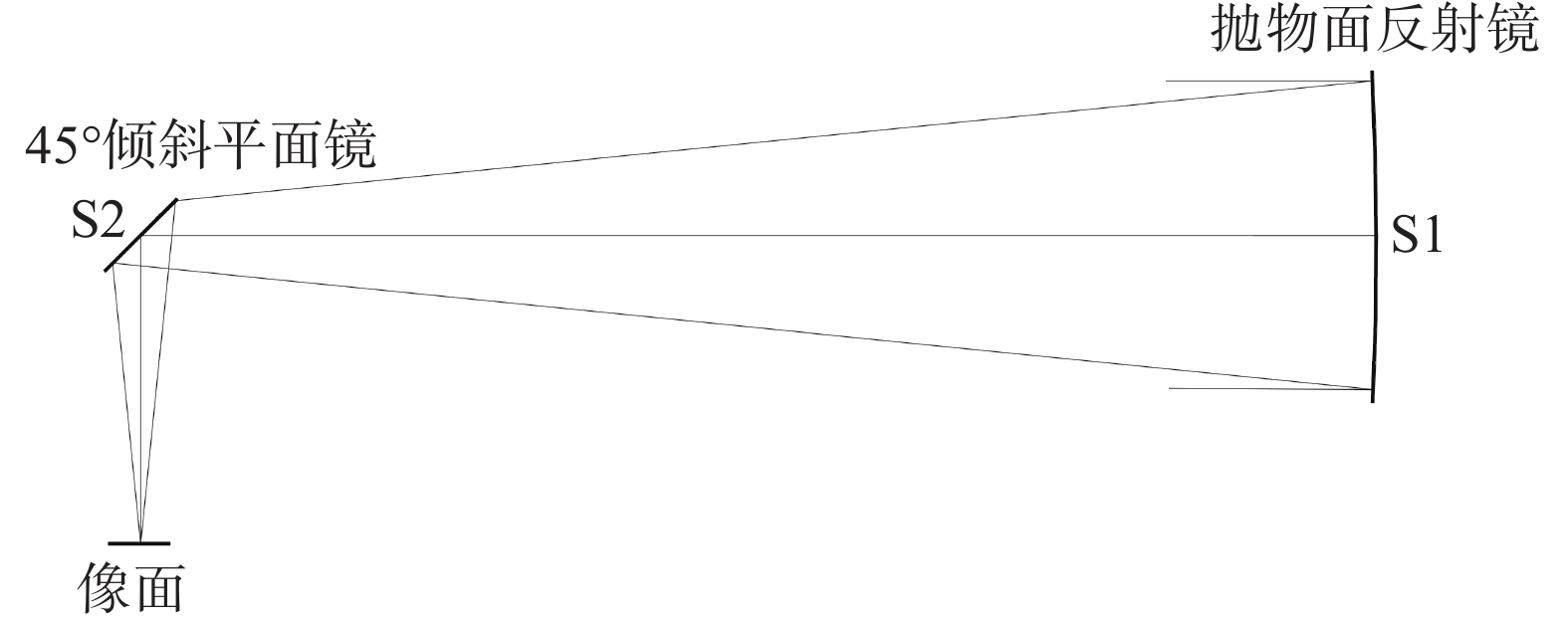
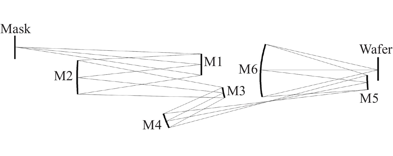
图 1 EUV投影系统结构。物方离轴视场高度为134~142 mm
Figure 1. Optical layout of the EUV projection system. The object-side off-axis field height ranges from 134 mm to 142 mm
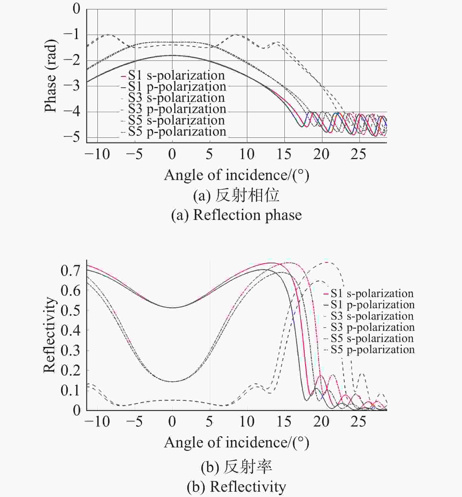
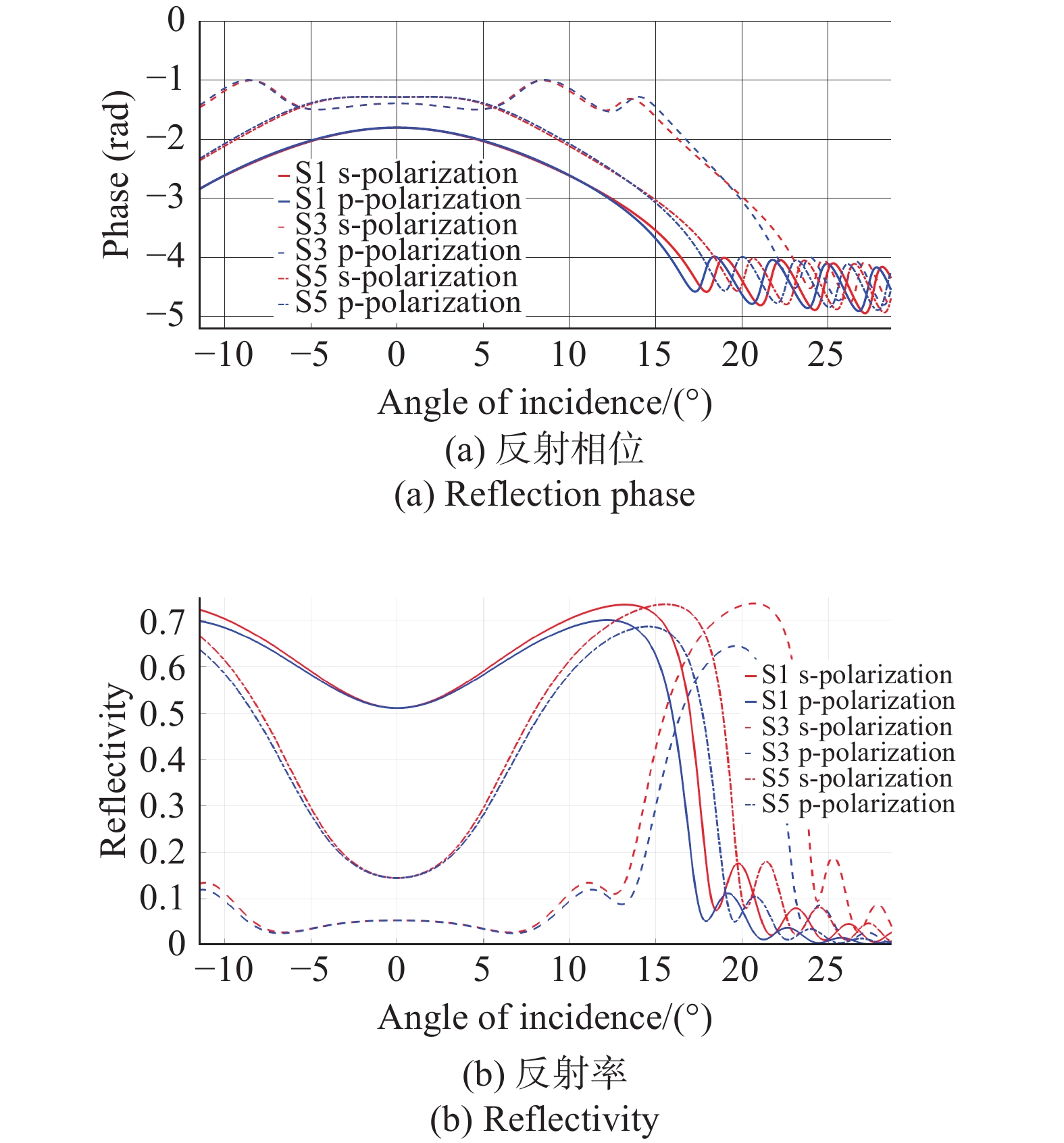
图 2 修正均匀膜层的反射相位和反射率随入射角的变化。实线、虚线和点划线分别表示表面1、3、5膜层反射特性
Figure 2. Reflection phase and reflectivity of the corrected uniform multilayer coating versus angle of incidence. The solid, dashed, and dash-dotted curves correspond to surfaces 1, 3, and 5, respectively
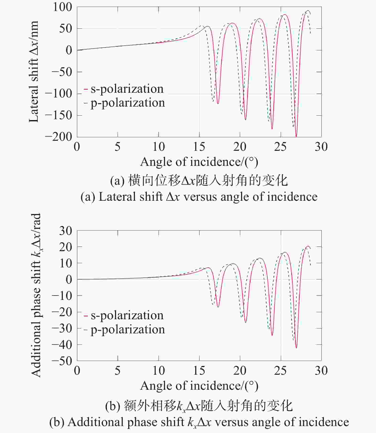
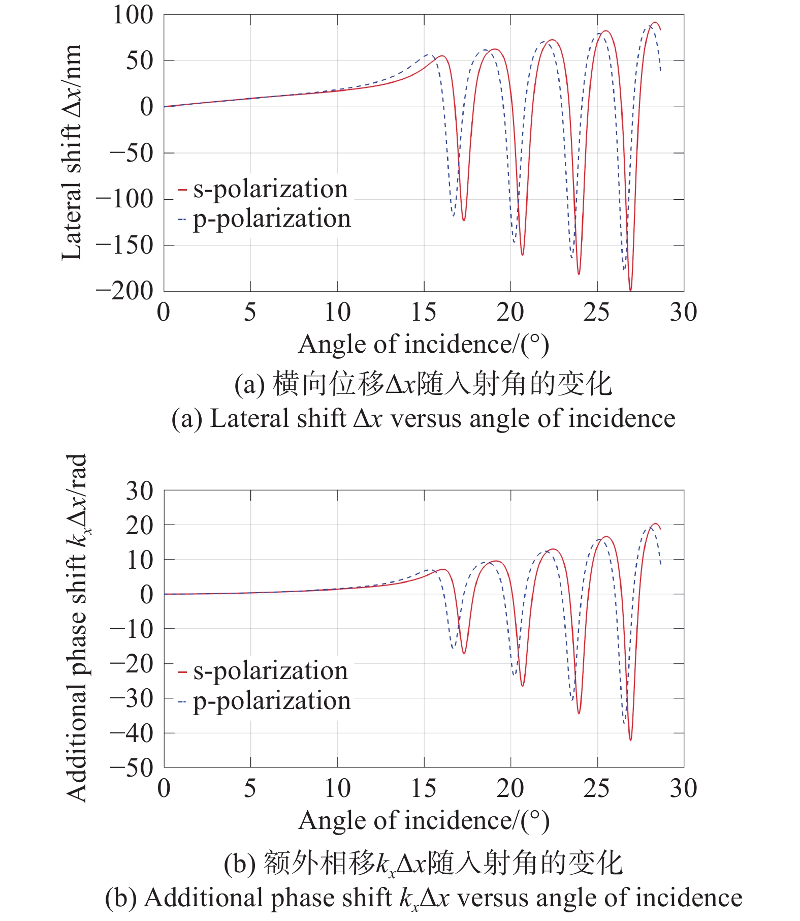
图 3 横向位移和额外相移随入射角的变化,入射角范围0~28°
Figure 3. Coating-induced lateral shift and the associated additional phase versus angle of incidence (AOI = 0–28°)
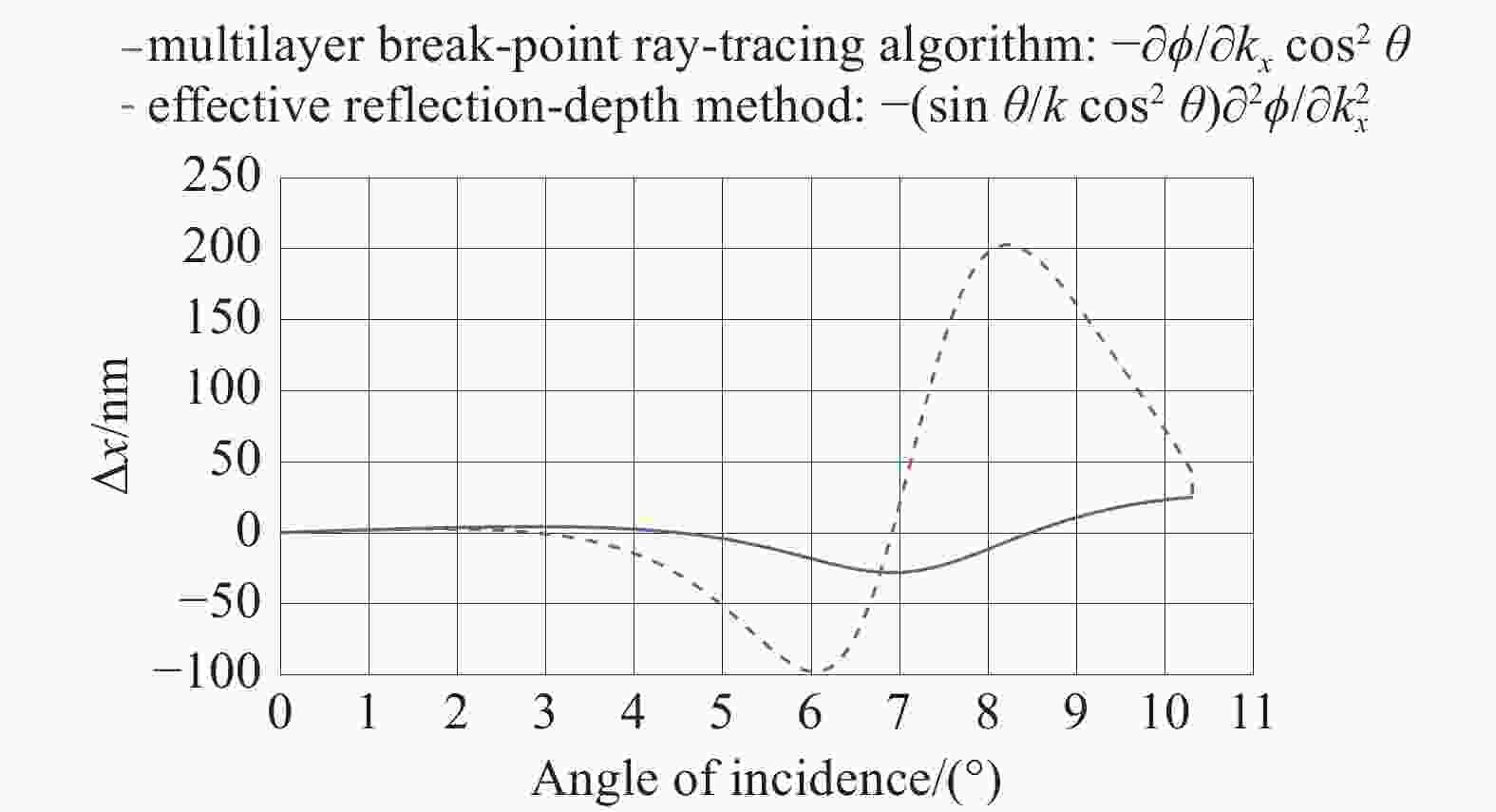
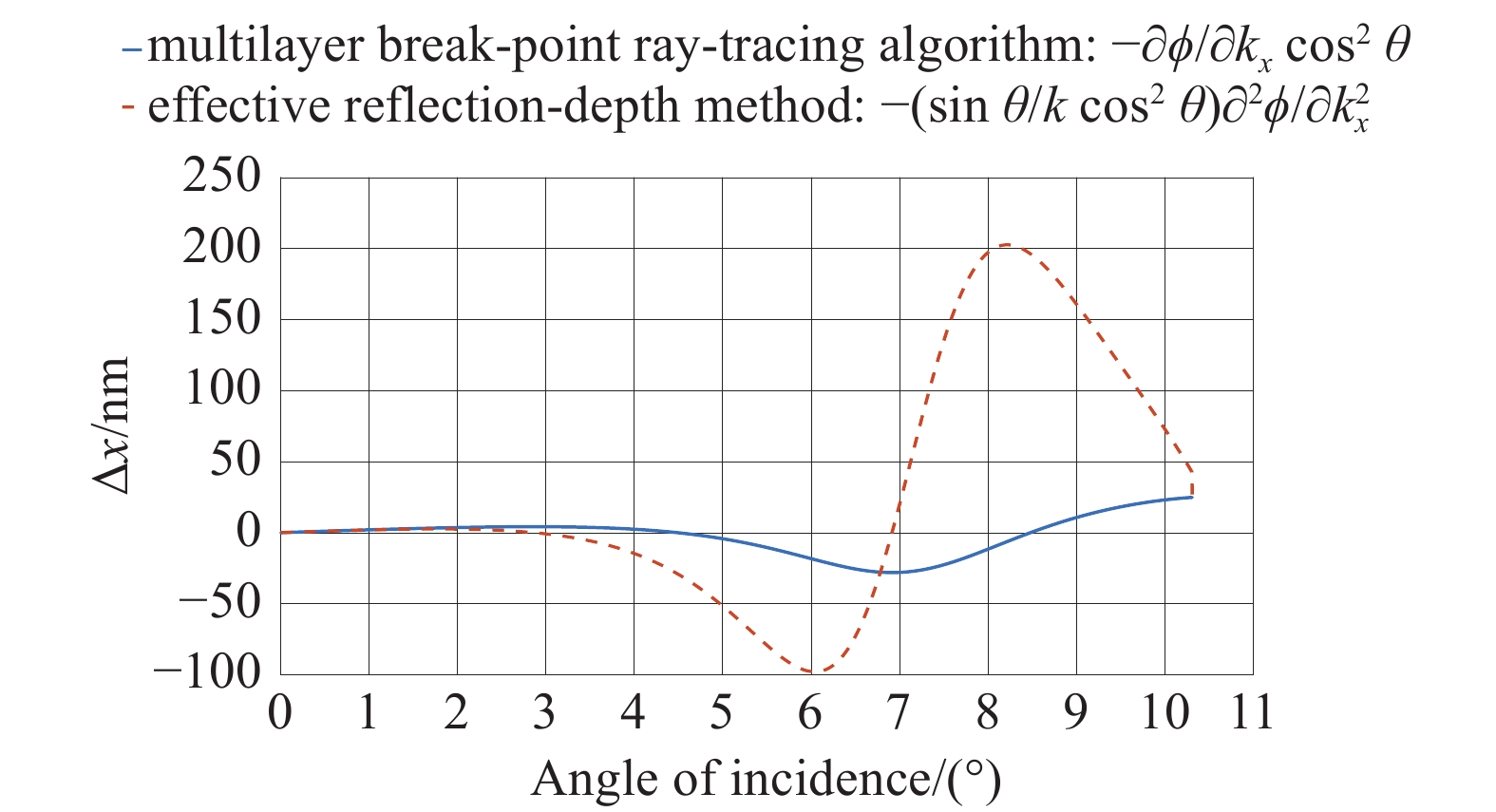
图 4 膜层断点追迹算法与有效反射深度算法计算的横向位移比较。二者在小角度下具有良好的一致性
Figure 4. Comparison of the lateral shift computed by the multilayer break-point ray-tracing method and the effective reflection-depth method. The two approaches agree well at small angles of incidence
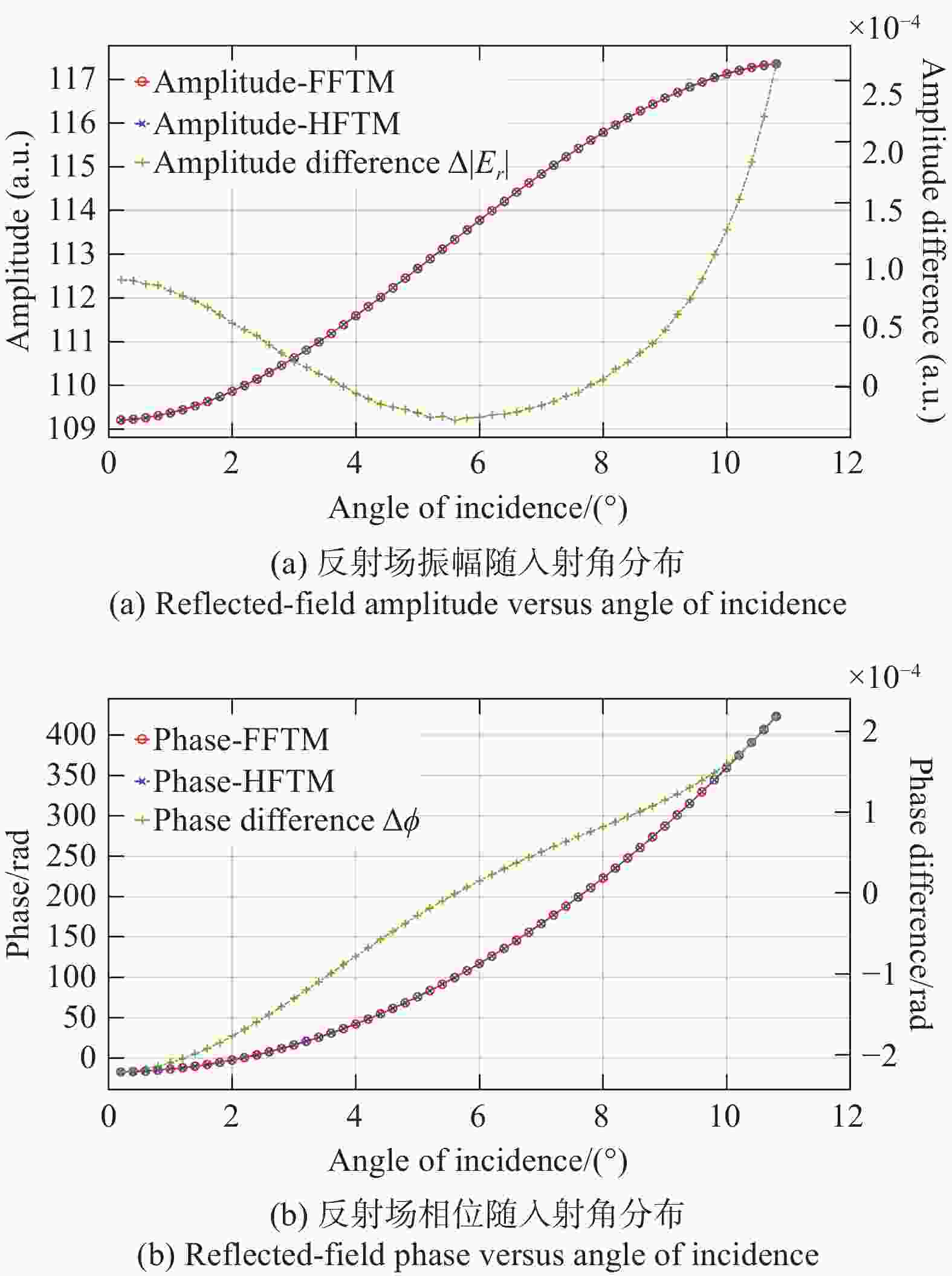
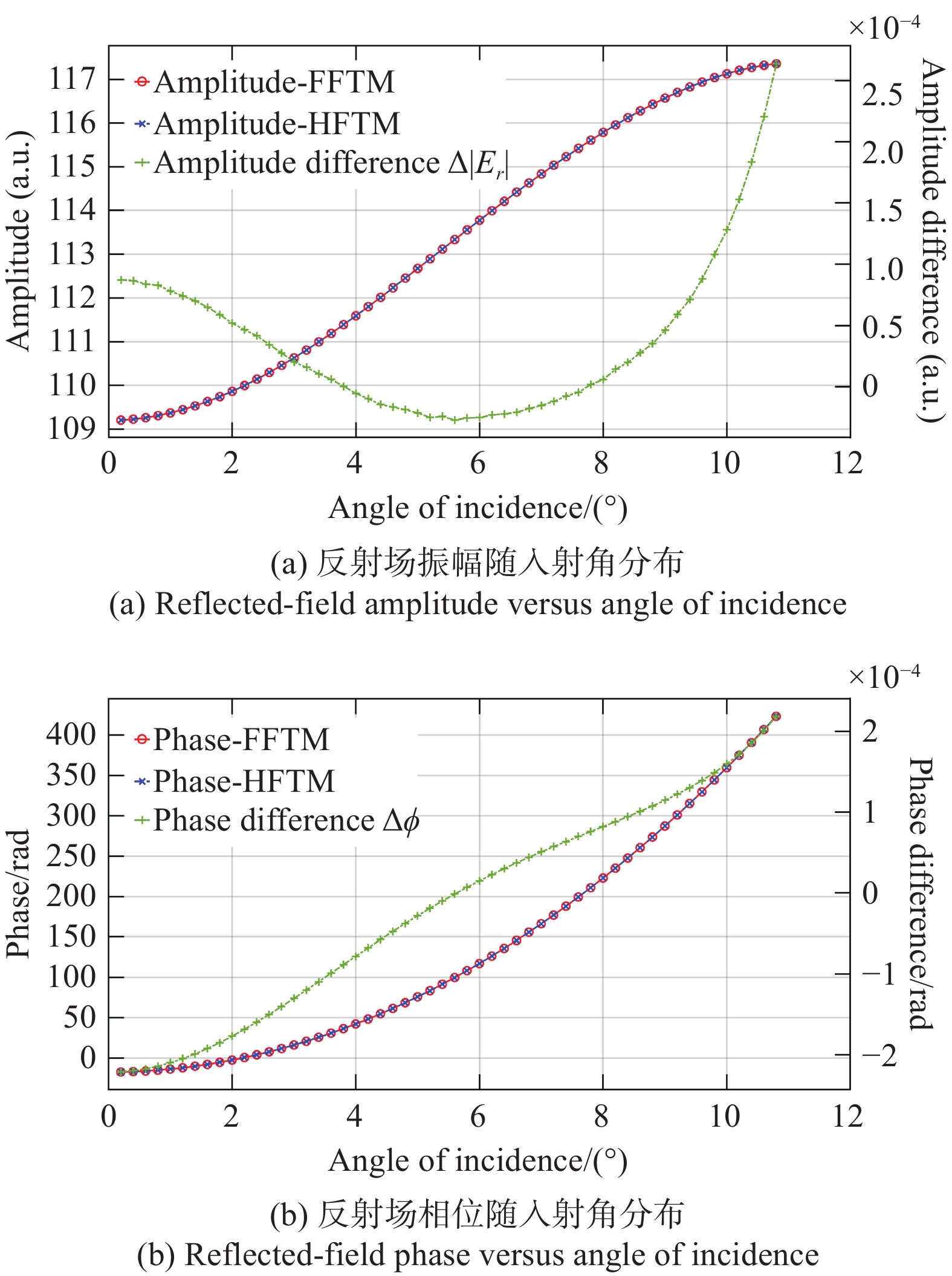
图 5 FFTM与HFTM计算的反射场振幅与相位随入射角分布情况。振幅、相位曲线对应左y轴,差值曲线对应右y轴
Figure 5. Reflected-field amplitude and phase versus angle of incidence calculated using FFTM and the HFTM. The amplitude/phase curves correspond to the left y-axis, and the difference curves correspond to the right y-axis

图 6 比较不同波段膜层影响的反射系统
Figure 6. Test reflective system used to compare coating-induced effects at different wavelength bands
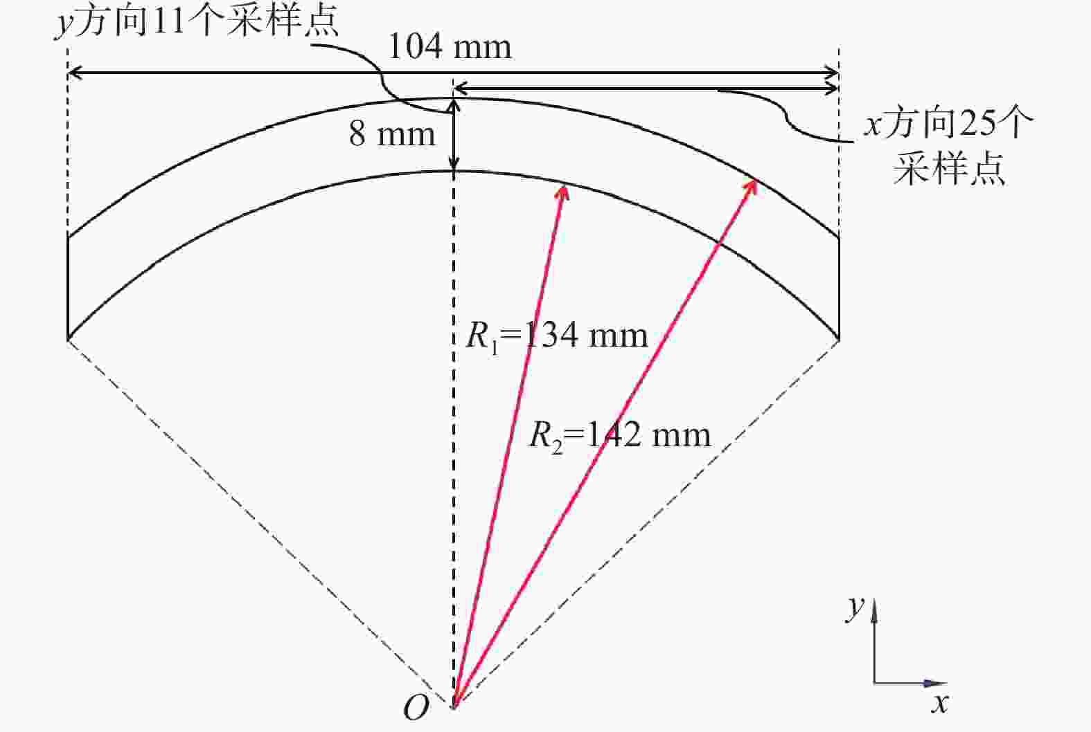
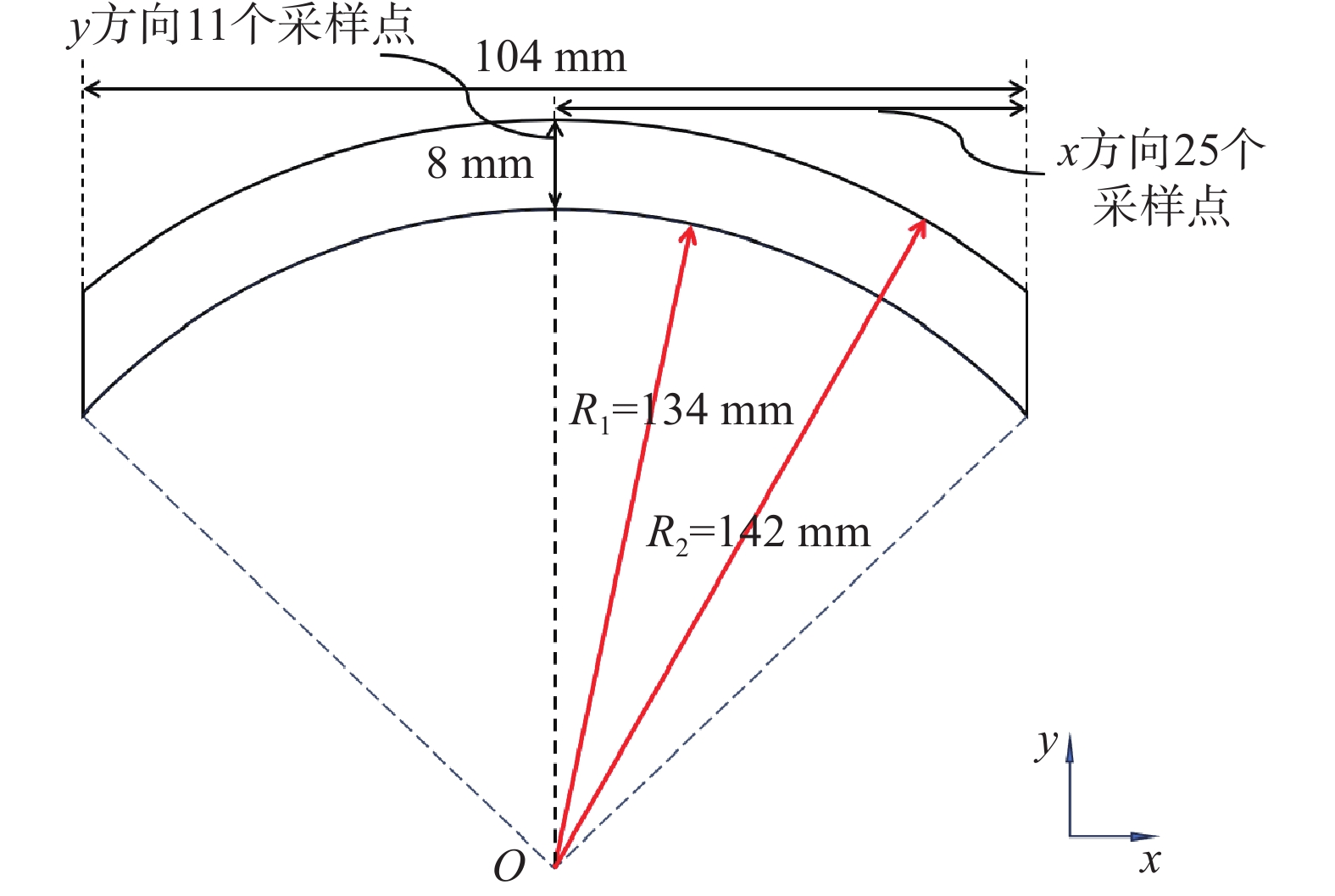
图 7 弧形视场形状及视场采样数
Figure 7. Curved scanning field and the corresponding field-sampling grid
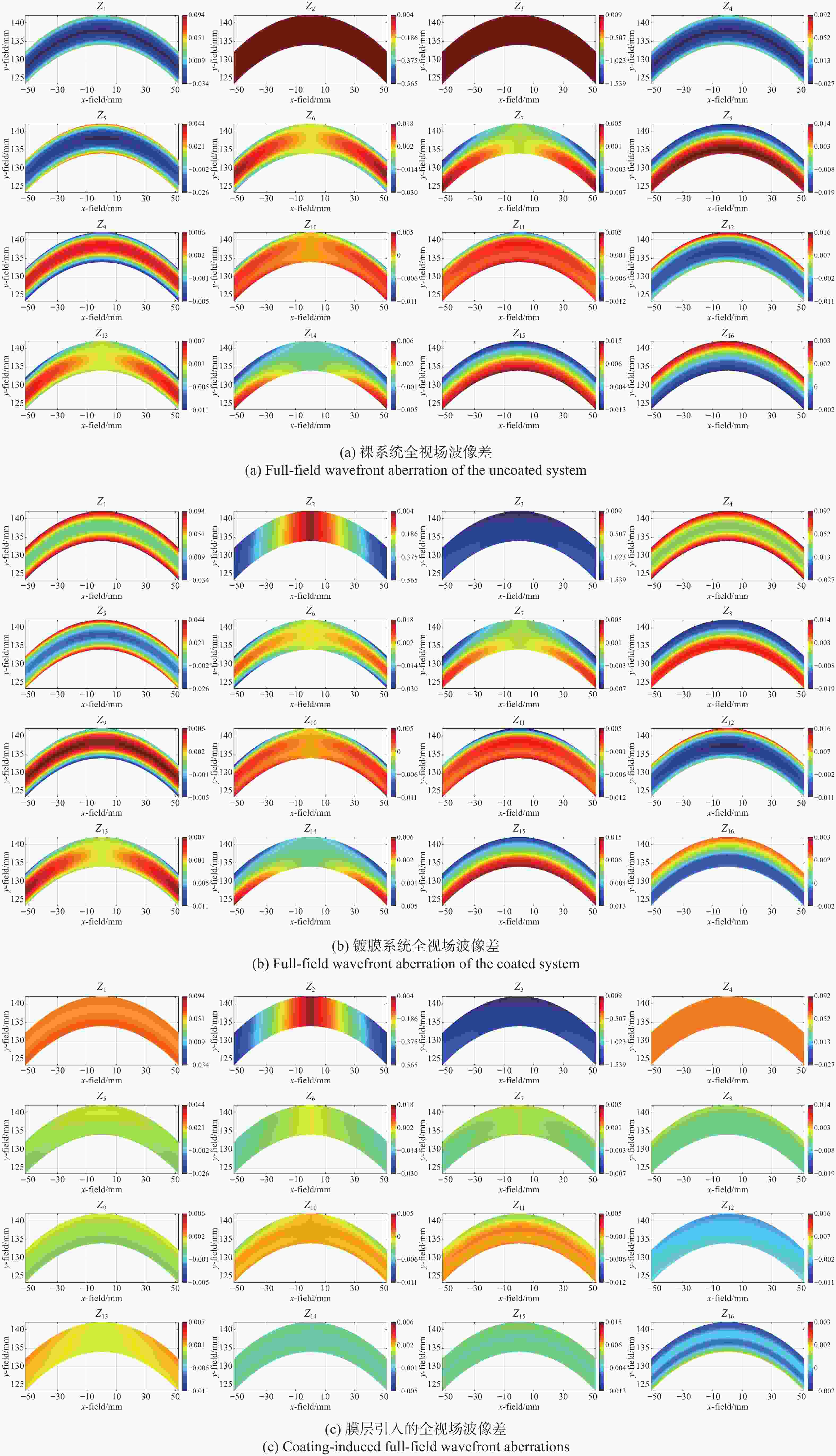
图 8 裸系统、镀膜系统及膜层引入波像差的前16项Zernike系数全视场分布。(a)、(b)、(c)中相同Zernike项绘制范围一致
Figure 8. Full-field maps of the first 16 Fringe-Zernike coefficients for (a) the uncoated system, (b) the coated system, and (c) the coating-induced aberration (coated minus uncoated). For each Zernike term, the color scale limits are kept identical in (a)–(c)
表 1 EUV系统各表面平均入射角和膜层厚度
Table 1. Average incidence angle and coating thickness of each surface in the EUV system
表面序号 平均入射角/° Si/nm Mo/nm 1 6.5034 4.2272 2.8181 2 6.5397 4.2275 2.8183 3 17.6011 4.4063 2.9375 4 8.3387 4.2449 2.8299 5 10.6555 4.2737 2.8491 6 3.7275 4.2089 2.8059  下载: 导出CSV
表 2 倾斜平面镜镀膜前后波前RMS。对600 nm和
1100 nm采取2种膜层形式,括号中数据是镀有膜系一的波前RMSTable 2. Wavefront RMS of a tilted plane mirror before and after coating. Two alternative multilayer designs are used for the 600-nm and
1100 -nm cases. The data in parentheses corresponding to the wavefront RMS with coating type I applied波长/nm 镀膜前RMS(λ) 镀膜后RMS(λ) 13.4 0.0000 0.1691 600 0.0000 0.0440 (0.0069 )1100 0.0000 0.0203 (0.0038 )
下载: 导出CSV
表 3 裸系统和镀膜系统的各Zernike项沿视场变化的RMS(单位:λ@13.4 nm)
Table 3. Field-dependent RMS of each Fringe-Zernike term for the uncoated and coated systems (unit: λ@13.4 nm)
Zernike项 未镀膜 镀膜 Z2 0.00121 0.31954 Z3 0.00537 1.41882 Z4 0.01855 0.05474 Z5 0.01623 0.01565 Z6 0.00752 0.00727 Z7 0.00242 0.00223 Z8 0.01071 0.00995 Z9 0.00323 0.00387 Z10 0.00165 0.00213 Z11 0.00225 0.00296 Z12 0.00605 0.00660 Z13 0.00278 0.00304 Z14 0.00184 0.00181 Z15 0.00806 0.00790 Z16 0.00143 0.00111
下载: 导出CSV
表 4 对x2myn正交化的前8项系数矩阵
Table 4. Coefficient matrix of the first eight terms in the orthogonalization of x2myn
1 y y2 y3 y4 x2 x2y x2y2 1.000 0 0 0 0 0 0 0 −34.910 36.832 0 0 0 0 0 0 1.015E3 −2.153E3 1.142E3 0 0 0 0 0 −2.993E4 9.555E5 −1.016E5 3.600E4 0 0 0 0 4.701E3 −1.531E4 1.654E4 −5.934E3 5.5765 0 0 0 6.466E3 −1.799E4 1.646E4 −4.941E3 −301.235 319.7468 0 0 −8.479E4 2.652E5 −2.763E5 9.594E4 1.101E4 −2.341E4 1.244E4 0 4.543E4 −1.434E5 1.509E5 −5.291E4 −1.167E5 3.743E5 −4.001E5 1.425E5
下载: 导出CSV
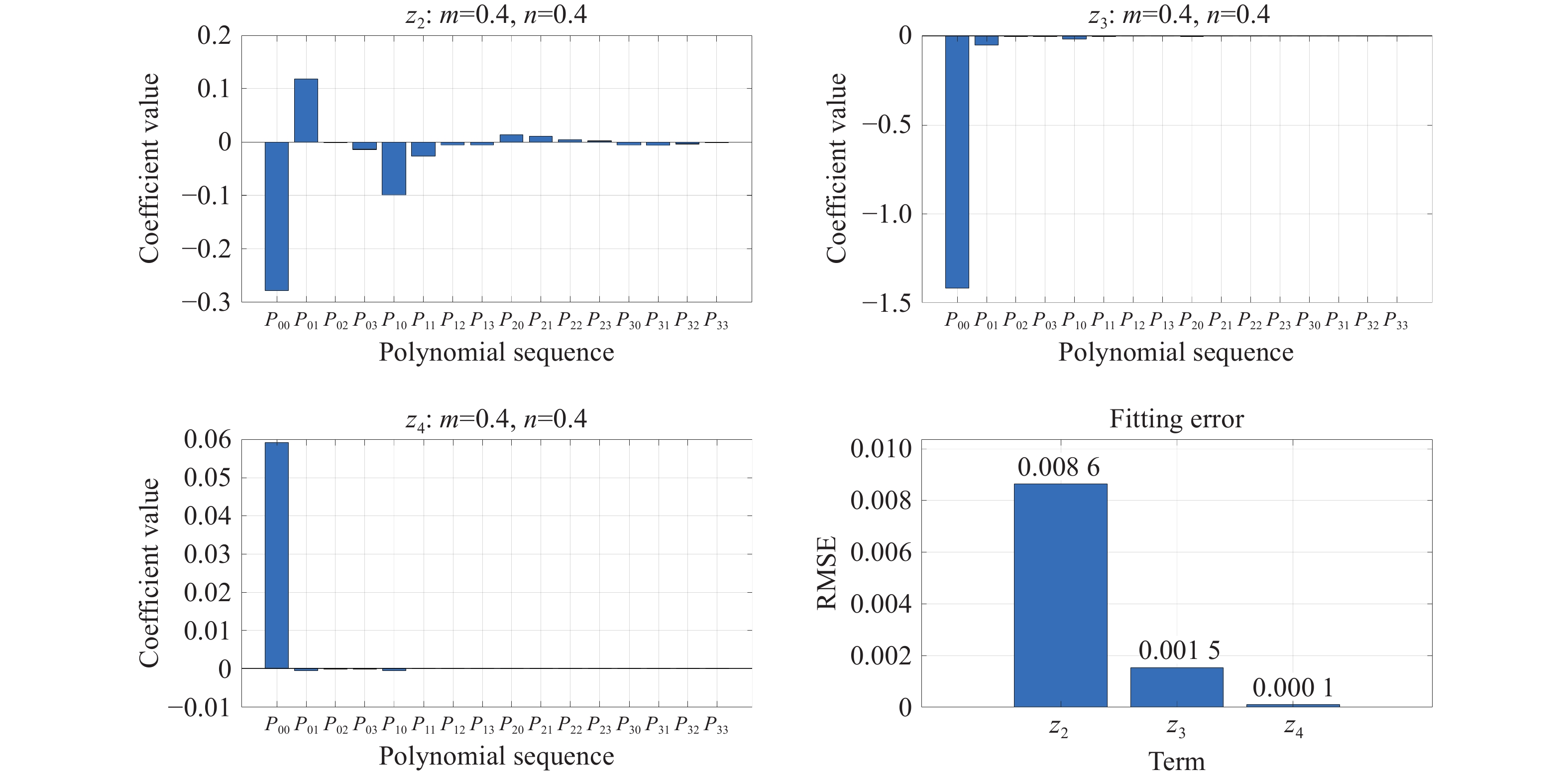
表 5 正交多项式拟合的Zernike系数的视场分布(单位:λ@13.4 nm)
Table 5. Field dependence of Zernike coefficients described by the orthogonal polynomial fitting (unit: λ@13.4 nm)
m n Z2 Z3 Z4 Z5 Z6 Z7 Z8 Z9 0 0 −0.278 −1.419 0.059 0.012 −0.005 −0.001 −0.004 0.001 0 1 0.118 −0.053 −0.001 0.002 0.002 0.000 0.000 0.000 0 2 0.000 −0.005 0.000 0.000 0.000 0.000 0.000 0.000 0 3 −0.014 −0.003 0.000 0.000 0.000 0.000 0.000 0.000 1 0 −0.099 −0.016 0.000 0.000 −0.002 0.000 0.001 0.000 1 1 −0.027 −0.004 0.000 0.000 0.000 0.000 0.000 0.000 1 2 −0.005 0.001 0.000 0.000 0.000 0.000 0.000 0.000 1 3 −0.005 0.001 0.000 0.000 0.000 0.000 0.000 0.000 2 0 0.014 −0.004 0.000 0.000 0.000 0.000 0.000 0.000 2 1 0.011 0.003 0.000 0.000 0.000 0.000 0.000 0.000 2 2 0.005 0.000 0.000 0.000 0.000 0.000 0.000 0.000 2 3 0.002 0.000 0.000 0.000 0.000 0.000 0.000 0.000 3 0 −0.005 0.003 0.000 0.000 0.000 0.000 0.000 0.000 3 1 −0.006 0.000 0.000 0.000 0.000 0.000 0.000 0.000 3 2 −0.003 0.000 0.000 0.000 0.000 0.000 0.000 0.000 3 3 −0.001 0.000 0.000 0.000 0.000 0.000 0.000 0.000 RMS 0.320 1.420 0.059 0.013 0.006 0.001 0.004 0.001 RMSE 0.0086 0.0015 0.0001 0.0000 0.0000 0.0000 0.0000 0.0000
下载: 导出CSV
表 6 EUV裸系统和镀膜后的波前RMS(单位:λ@13.4 nm)
Table 6. Full-field RMS wavefront error of the EUV system before and after coating (unit: λ at 13.4 nm)
RMS RMS(去除倾斜) 裸系统 0.01619 0.01588 镀膜 0.8422 0.04486 镀膜后离焦 0.6576 0.01707
下载: 导出CSV
-
[1] CIESIELSKI R, SAADEH Q, PHILIPSEN V, et al. Determination of optical constants of thin films in the EUV[J]. Applied Optics, 2022, 61(8): 2060-2078. doi: 10.1364/AO.447152 [2] MACLEOD H A. Thin-Film Optical Filters[M]. 4th ed. Boca Raton: CRC Press, 2010. [3] MA J Y, REN J L, ZHANG J H, et al. Quantum imaging using spatially entangled photon pairs from a nonlinear metasurface[J]. eLight, 2025, 5(1): 2. doi: 10.1186/s43593-024-00080-8 [4] MA SH J, YAN L, YE H K, et al. Polarization aberration in catadioptric anamorphic optical system[J]. Proceedings of SPIE, 2023, 12765: 127651S. [5] HE CH, ANTONELLO J, BOOTH M J. Vectorial adaptive optics[J]. eLight, 2023, 3(1): 23. doi: 10.1186/s43593-023-00056-0 [6] 吕金锦, 祝青霞, 路易, 等. 正交线偏振光成像制导镜头的设计与仿真[J]. 飞控与探测, 2023, 6(2): 23-28.LYU J J, ZHU Q X, LU Y, et al. Design and simulation of orthogonal linearly polarized imaging guidance lens[J]. Flight Control & Detection, 2023, 6(2): 23-28. (in Chinese). [7] 罗敬, 陈兴达, 吕凝睿, 等. 光学系统偏振特性影响抑制方法综述[J]. 中国光学(中英文), 2025, 18(5): 979-1015. doi: 10.37188/CO.2025-0066LUO J, CHEN X D, LV N R, et al. A review of methods for suppressing the influence of polarization characteristics in optical systems[J]. Chinese Optics, 2025, 18(5): 979-1015. (in Chinese). doi: 10.37188/CO.2025-0066 [8] LIU X L, HUANG Y, YAN X, et al. The correction method for wavefront aberration caused by spectrum-splitting filters in multi-modal optical imaging system[J]. Photonics, 2024, 11(9): 876. doi: 10.3390/photonics11090876 [9] BAL M F, SINGH M, BRAAT J J M. Optimization of multilayer reflectors for extreme ultraviolet lithography[J]. Journal of Micro/Nanolithography, MEMS, and MOEMS, 2004, 3(4): 537-544. doi: 10.1117/1.1793171 [10] REILEY D J, CHIPMAN R A. Coating-induced wavefront aberrations[J]. Proceedings of SPIE, 1992, 1746: 139-146. [11] LIANG CH, DESCOUR M R, SASIAN J M, et al. Multilayer-coating-induced aberrations in extreme-ultraviolet lithography optics[J]. Applied Optics, 2001, 40(1): 129-135. doi: 10.1364/AO.40.000129 [12] SMITH B W. Optical considerations of EUVL wavelength, NA, and multilayers at large angles[J]. Proceedings of SPIE, 2025, 13424: 1342402. [13] BROVELLI L R, KELLER U. Simple analytical expressions for the reflectivity and the penetration depth of a Bragg mirror between arbitrary media[J]. Optics Communications, 1995, 116(4-6): 343-350. doi: 10.1016/0030-4018(95)00084-L [14] 王君, 金春水, 王丽萍, 等. 极紫外光刻投影物镜中多层膜分析模型的建立及应用[J]. 光学学报, 2014, 34(8): 0811002. doi: 10.3788/AOS201434.0811002WANG J, JIN CH SH, WANG L P, et al. Foundation and application of model for multilayers analysis in extreme ultra-violet lithography projection[J]. Acta Optica Sinica, 2014, 34(8): 0811002. (in Chinese). doi: 10.3788/AOS201434.0811002 [15] 来搏, 蒋励, 齐润泽, 等. 40~90 nm波段极紫外多层膜研究进展[J]. 光学 精密工程, 2024, 32(9): 1293-1306. doi: 10.37188/OPE.20243209.1293LAI B, JIANG L, QI R Z, et al. Research developments of extreme ultra-violet multilayers for 40-90 nm[J]. Optics and Precision Engineering, 2024, 32(9): 1293-1306. (in Chinese). doi: 10.37188/OPE.20243209.1293 [16] HENKE B L, GULLIKSON E M, DAVIS J C. X-ray interactions: photoabsorption, scattering, transmission, and reflection at E = 50-30, 000 eV, Z = 1-92[J]. Atomic Data and Nuclear Data Tables, 1993, 54(2): 181-342. doi: 10.1006/adnd.1993.1013 [17] ZHANG Y, ZHANG S T, ZHENG Y H, et al. Algorithm for accurate and efficient calculation of coating-induced effects[J]. Optics Express, 2024, 32(17): 29279-29290. doi: 10.1364/OE.527842 [18] GOODMAN J W. Introduction to Fourier Optics[M]. 3rd ed. Englewood: Roberts & Co. Publishers, 2005. [19] MANSURIPUR M. Classical Optics and its Applications[M]. 2nd ed. Cambridge: Cambridge University Press, 2009. [20] WANG Z ZH, BALADRON-ZORITA O, HELLMANN C, et al. Theory and algorithm of the homeomorphic Fourier transform for optical simulations[J]. Optics Express, 2020, 28(7): 10552-10571. doi: 10.1364/OE.388022 [21] SASIÁN J. Introduction to Aberrations in Optical Imaging Systems[M]. Cambridge: Cambridge University Press, 2012. [22] CHAI X Y, ZHANG H B, LIN X Y, et al. Method for orthogonal fitting of arbitrary shaped aperture wavefront and aberration removal[J]. Optical Engineering, 2024, 63(5): 054112. doi: 10.1117/1.oe.63.5.054112 [23] BAUER A, TAKAKI N, ROLLAND J P. Design methods for imaging with freeform optics[J]. Optica, 2025, 12(11): 1775-1793. doi: 10.1364/OPTICA.575611 [24] CHAI X Y, LIN X Y, CHEN H T, et al. Zernike polynomials fitting of arbitrary shape wavefront[J]. Proceedings of SPIE, 2024, 13069: 1306912. doi: 10.1117/12.3023145 -

 下载:
下载:


计量
- 文章访问数: 230
- HTML全文浏览量: 91
- PDF下载量: 52
- 被引次数: 0
