Methodology for predicting optical system performance when subjected to static stresses
doi: 10.3788/CO.20160906.0678
-
摘要: 本文通过计算预测光学性能的方法表征在光学系统组装和外界环境因素影响下的光学系统灵敏度。该方法即通过调制传递函数来表征静态机械应力对光学物镜性能的影响。采用光学干涉仪对经过加工、组装且存在机械应力的光学物镜进行测试,并比较实验调制传递函数与计算模拟分析的调制传递函数。结果表明,计算结果与实验结果相符,证实了本文方法的有效性。Abstract: High performance optical systems are characterized by high sensitivity to assembly procedure of the system and to any sensible change in environmental conditions. This sensitivity issue is handled in this paper through a methodology allowing a computational prediction of optical performance when the opto-mechanical system is subject to some external factors. This paper explains the methodology through an example of an optical objective of excellent performance undergoing static mechanical stresses which degrade the performance expressed by an MTF diagram. Then the objective is manufactured, assembled, and an optical interferometer is used to test the objective when stress is retained; and the experimental results of degraded MTF are compared to the analytical MTF. The excellent matching between the two sets of results confirms the validity of the proposed methodology.
-
Key words:
- predicting optical performance /
- assembly of optical system /
- tensile torque /
- MTF /
- objective /
- Ansys /
- Matlab
-
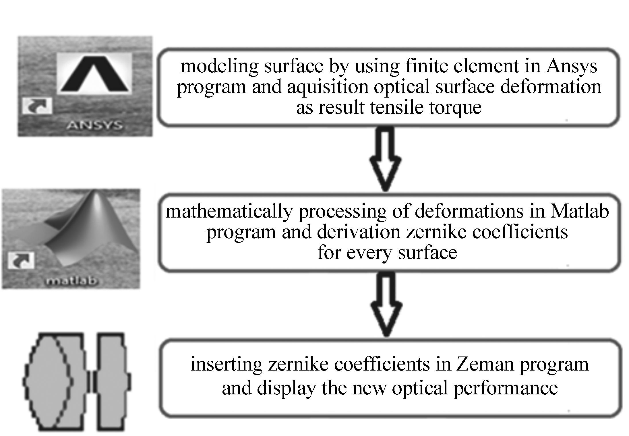
Figure 1. General scheme for predicting optical performance through the static structural analysis[3]
Table 1. Parameters of the designed objective
Surfaces number Radius/mm Thickness/mm Optical diameter/mm Glass material (Stop) 187.5 7.5 60 H-ZF52A 2 -305.5 38.753 59.46 Air 3 85.70 8 40.31 H-BAK4 4 -88.51 5 38.70 H-ZF52A 5 192.31 89.425 36.24 Air Table 2. Characteristics of the materials used in the modeling
Parameters Aluminum Glass Young modulus/(N·m-2) 7.1×10¹⁰ 9.67×10¹⁰ Poisson′s ratio 0.33 0.226 Table 3. Tensile torques values as a function of retainer displacement
Moment (N·m) Force (N) Displacement (μm) 3.06 51 30 3.904 2 65.07 32.4 5.082 84.7 34.8 5.902 2 98.37 36 Table 4. Zernike coefficients for a set of tensile torques
Tensile torque/(N·m) Piston(Z1) Third Sphere(Z9) Fifth Sphere(Z16) Surface 1 Surface 2 Surface 1 Surface 2 Surface 1 Surface 2 3 8.49×10⁻³ -0.017 3 7.84×10⁻⁵ -1.27×10⁻⁴ 7.51×10⁻⁷ 9.41×10⁻⁷ 4 5.43×10⁻³ -3.14×10⁻³ 1.88×10⁻⁴ -7.40×10⁻⁵ 3.49×10⁻⁷ 2.51×10⁻⁷ 5 8.31×10⁻³ -7.13×10⁻³ 1.43×10⁻⁴ -1.45×10⁻⁴ 2.01×10⁻⁷ 9.63×10⁻⁷ 6 0.012 5 -0.031 7 1.35×10⁻⁴ -1.62×10⁻⁴ 2.47×10⁻⁷ 2.82×10⁻⁷ Table 5. MTF values at typical spatial frequencies obtained by computation and experiment
6 N·m 5 N·m 4 N·m 3 N·m Spatial frequency MTF (computation) MTF (experiment) MTF (computation) MTF (experiment) MTF (computation) MTF (experiment) MTF (computation) MTF (experiment) 0 1.000 1.000 1.000 1.000 1.000 1.000 1.000 1.000 62.5 0.739 0.791 0.657 0.717 0.623 0.658 0.595 0.614 125 0.510 0.520 0.409 0.408 0.355 0.410 0.312 0.278 187.5 0.364 0.310 0.276 0.251 0.225 0.209 0.186 0.130 250 0.304 0.268 0.225 0.192 0.184 0.160 0.154 0.081 312.5 0.275 0.251 0.226 0.189 0.199 0.140 0.176 0.115 375 0.231 0.239 0.210 0.184 0.197 0.165 0.187 0.179 437.5 0.136 0.153 0.117 0.135 0.106 0.091 0.099 0.125 500 0.057 0.071 0.039 0.066 0.030 0.054 0.022 0.037 562.5 0.006 0.015 0.017 0.017 0.041 0.022 0.012 0.017 625 0.000 0.000 0.000 0.000 0.000 0.002 0.000 0.002 -
[1] KASUNIC K J. Optomechanical Systems Engineering[M]. New Jersey:John Wiley & Sons,Inc.,Hoboken,2015. [2] SCHWERTZ K,BURGE H. Field Guide to Optomechanical Design and Analysis[M], Bellingham:SPIE Press,2012. [3] DOYLE K B,GENBERG V L,MICHELSS G J. Integrated Optomechanical Analysis(2nd Edition)[M]. Bellingham:SPIE Press,2012. [4] KASUNIC K J,BURGE J,YODER P. Mounting of Optical Components[M]. Bellingham:SPIE Press,2013. [5] YODER P R. Parametric Investigations of Mounting-Induced Axial Contact Stresses in Individual Lens Elements[J]. SPIE,1993,1998:8-20. http://cn.bing.com/academic/profile?id=2115684958&encoded=0&v=paper_preview&mkt=zh-cn [6] SigFit is a product of Sigmadyne,Inc.,Rochester,New York[EB/OL]. http://www.sigmadyne.com. [7] GENBERG V,DOYLE K,MICHELS G. Making FEA results useful in optical analysis[J]. SPIE,2002,4769:24-33. http://cn.bing.com/academic/profile?id=2040583220&encoded=0&v=paper_preview&mkt=zh-cn [8] GENBERG V,DOYLE K,MICHELS G. Opto-Mechanical I/F for ANSYS[R]. Sigmadyne Company,2004:TT58. [9] DOYLE K B,GENBERG V L,MICHELS G J. Integrated optomechanical analysis of adaptive optical systems[J]. SPIE,2004,5178:20-25. http://cn.bing.com/academic/profile?id=2079749194&encoded=0&v=paper_preview&mkt=zh-cn [10] DOYLE K B,HOFFMAN J M,GENBERG V L,et al.. Stress Birefringence Modeling for Lens Design and Photonics[J]. SPIE,2002,4832:436-447. http://cn.bing.com/academic/profile?id=2037294897&encoded=0&v=paper_preview&mkt=zh-cn [11] DOYLE K,GENBERG V,MICHELS G,et al.. Numerical methods to compute optical errors due to stress birefringenc[J]. SPIE,2002,4769:34-42. http://cn.bing.com/academic/profile?id=2006713758&encoded=0&v=paper_preview&mkt=zh-cn [12] BOOTH M,WILSON T,SUN H B,et al.. Methods for the characterization of deformable membrane mirrors[J]. Applied Optics,2005,44(24):5131-5139. doi: 10.1364/AO.44.005131 [13] GENBERG V,MICHELS G,DOYLE K. Orthogonality of zernike polynomials[J]. SPIE,2002,4771:33-40. http://cn.bing.com/academic/profile?id=2033573001&encoded=0&v=paper_preview&mkt=zh-cn [14] Zemax Manual:Optical Design Program User's Guide 9-6-2009[M]. ZEMAX Development Corporation. [15] BUCKLEY-LEWIS D H. Friction behavior of glass and metals in contact with glass in various environments[R],Nasa Technical Note,1973,Nasa TN 0-7529. -


 下载:
下载:


