


-
摘要:
为了实现动态物体的三维轮廓测量,并克服传统傅里叶解调方法中由于不同载频频谱混叠而导致的测量精度的限制,以及彩色复合条纹投影技术中的颜色耦合问题,本文提出了一种基于快速迭代滤波的三频彩色条纹投影轮廓术。该方法首先通过CCD相机采集一帧彩色图像,其中
$R$ 、$G$ 、$B$ 通道分别携带了不同频率的变形条纹图像。然后,通过各分量互减去除干扰背景及噪音得到了频率混合的条纹图,接着利用快速迭代滤波将不同的频率条纹图进行分离和颜色解耦。随后,对由$R$ 、$G$ 、$B$ 通道分离的单频率的条纹图分别进行傅里叶变换,提取包裹相位信息。最后,为了实现精确的相位展开,本文首先采用空域解包裹算法展开低频相位,并基于此依次展开中频和高频相位,从而完成整个相位解包裹过程。仿真和实验结果表明,本文方法的相位展开精度比传统傅里叶方法提高约7倍,且相比其他单帧解调方法,本文方法精度最高,抗噪性能强,为高精度、动态实时三维测量提供了一种有效的技术方案。Abstract:In order to achieve real-time 3D measurement of dynamic objects and to overcome the measurement accuracy limitations caused by spectral aliasing of different carrier frequencies in traditional Fourier demodulation methods, as well as the color coupling problem in color composite stripe projection techniques, this paper proposes a three-frequency color stripe projection profilometry method based on fast iterative filtering. The method first captures a color image using a CCD camera, where the red, green, and blue channels carry gray stripe images with different carrier frequencies. Background interference is then reduced by component subtraction, followed by carrier frequency separation and color decoupling using fast iterative filtering. The subsequent application of the Fourier transform is applied to the carrier-frequency stripe images in the red, green, and blue channels enables the extraction of wrapped phase information. To achieve accurate phase unwrapping, a spatial domain unwrapping algorithm is employed. The low-frequency phase is first unwrapped, followed by the middle and high-frequency phases, which are unwrapped sequentially to complete the entire phase unwrapping process. The simulation and experimental results demonstrates that the proposed method exhibits a phase unwrapping accuracy that is 7 times higher than that of traditional Fourier methods. In comparison with other single-frame demodulation methods, the proposed method demonstrates superior accuracy and robust noise resistance, thus providing an effective technical solution for high-precision, dynamic real-time 3D measurement.
-
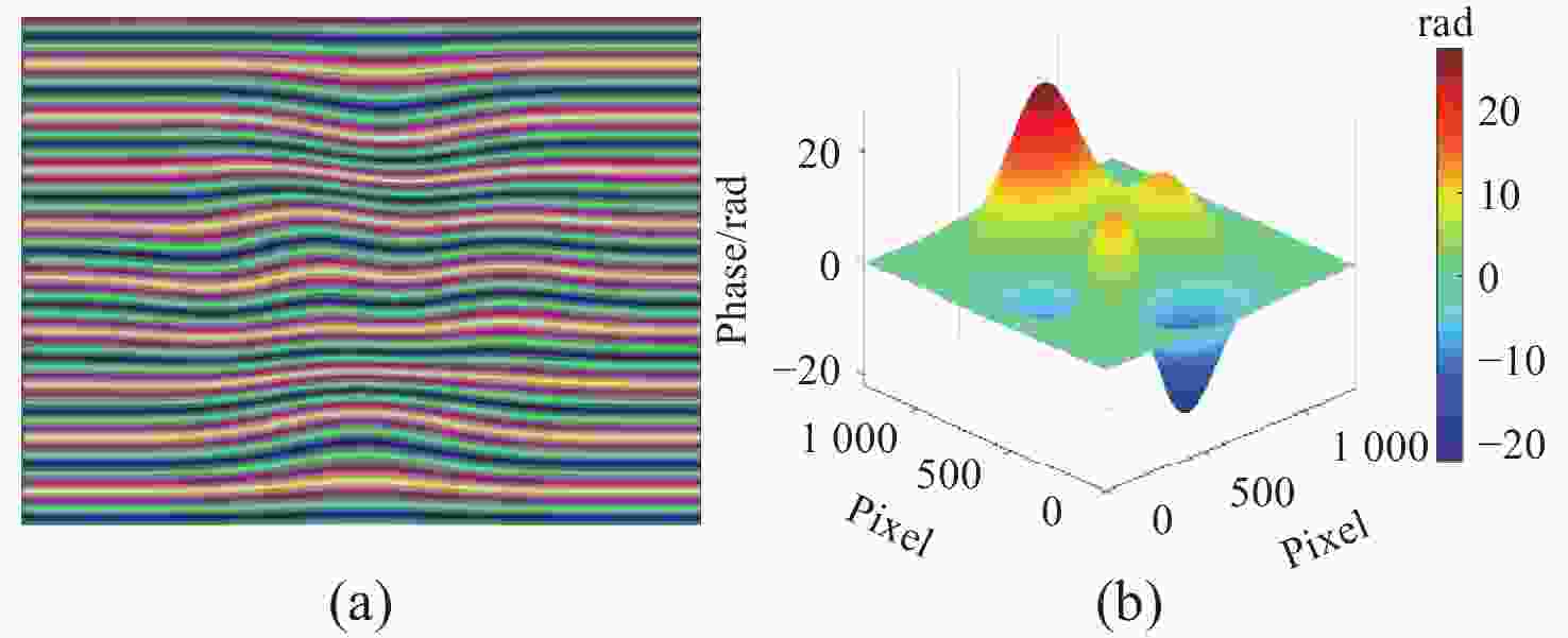
图 1 模拟条纹图和参考相位。(a)彩色条纹图;(b) Peaks相位
Figure 1. Simulated moiré pattern and reference phase. (a) color moiré pattern; (b) reference phase
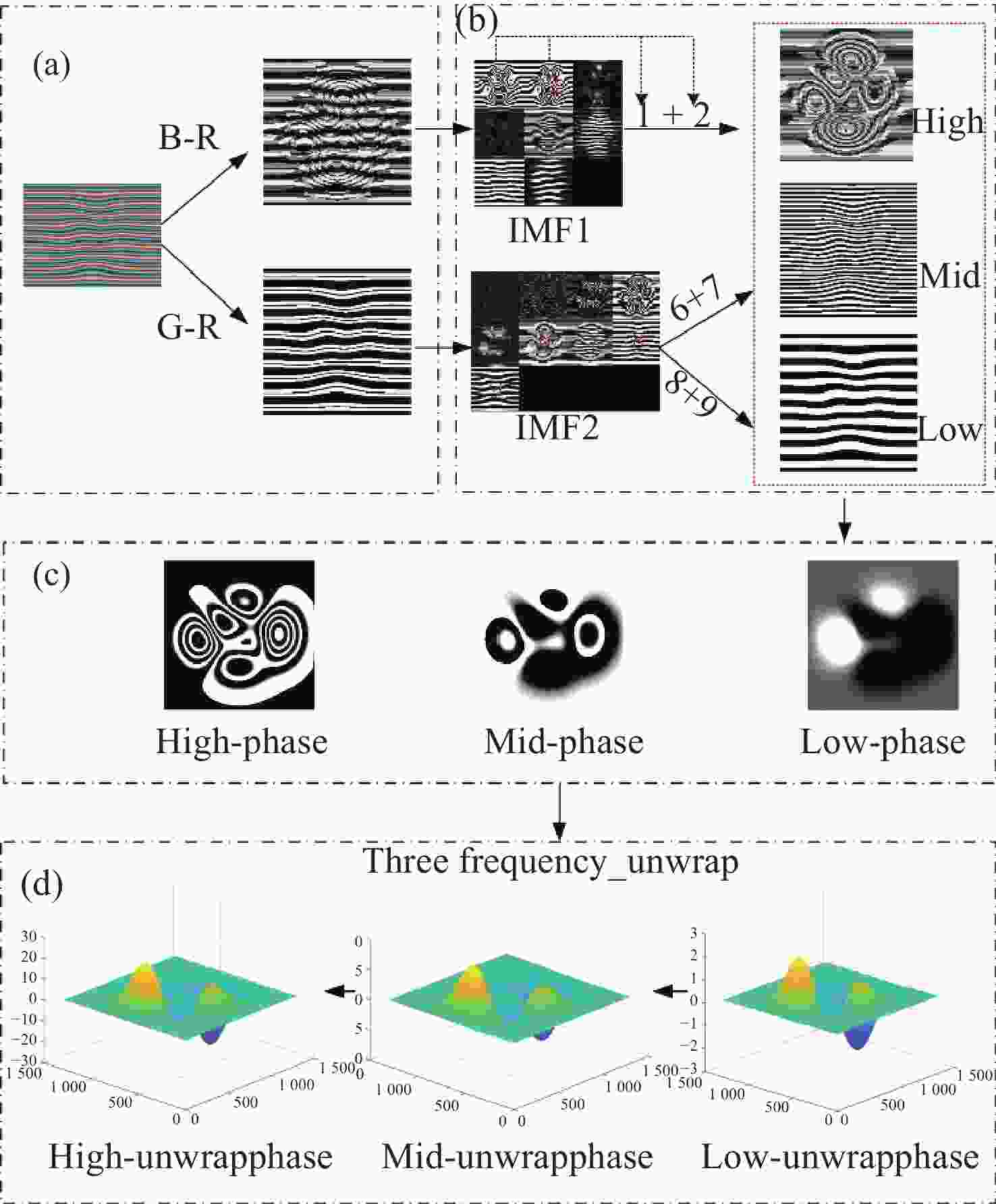
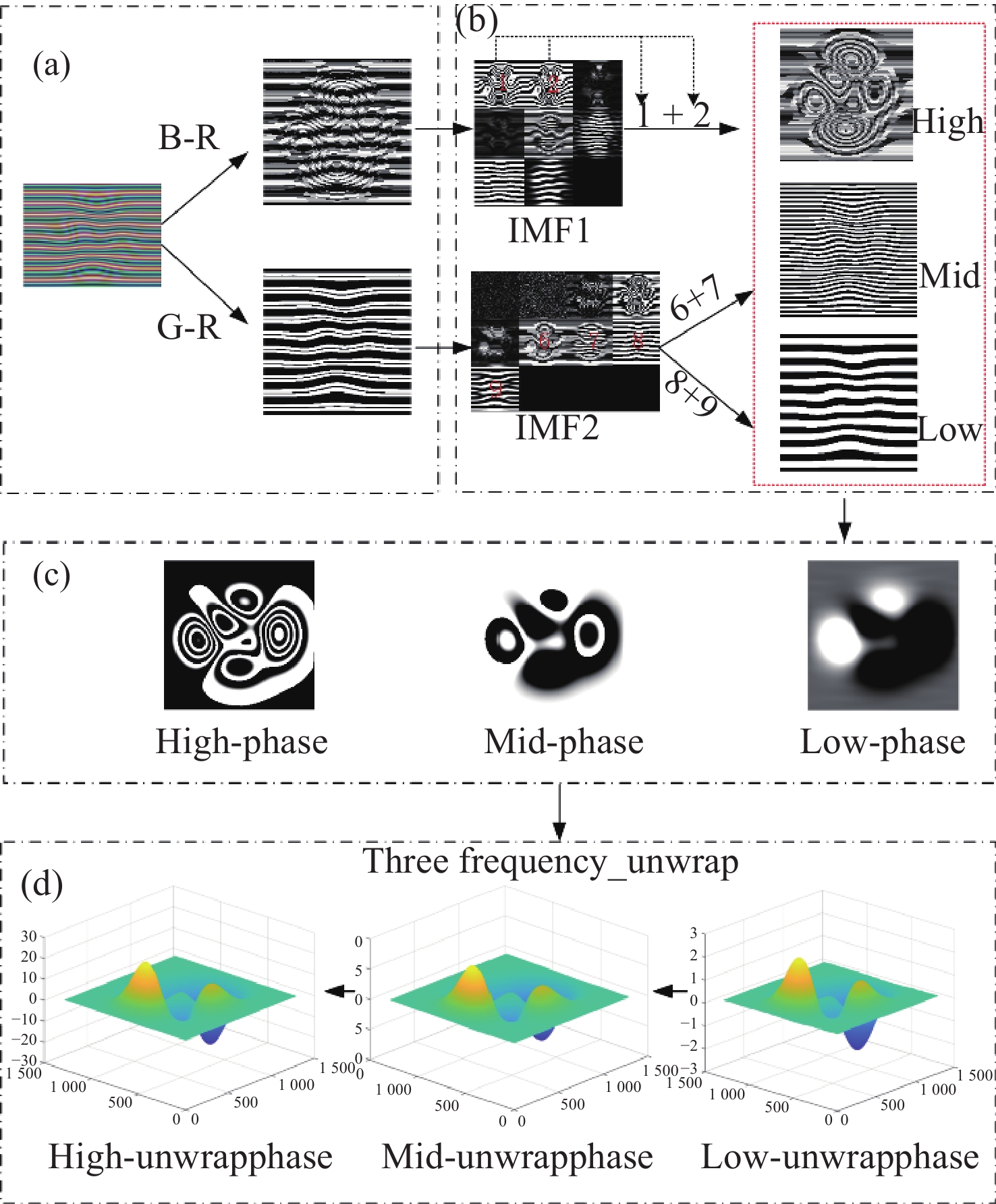
图 2 本文方法peak仿真实验包含4个模块。(a)通道互减消除背景;(b)获得高、中、低频分量;(c)对高、中、低频分量提取相位;(d)获得低、中、高频展开相位
Figure 2. The method in this peak simulation experiment includes four modules. (a) channel mutual subtraction to eliminate the background; (b) obtain the high, medium, and low-frequency components; (c) extract the phase of the high, medium, and low-frequency components; (d) obtain the phase expansion for the low-, medium-, and high-frequency components
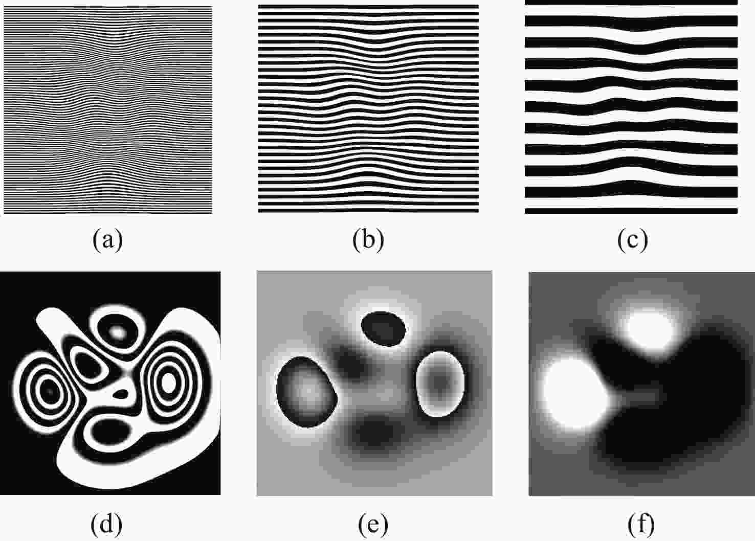
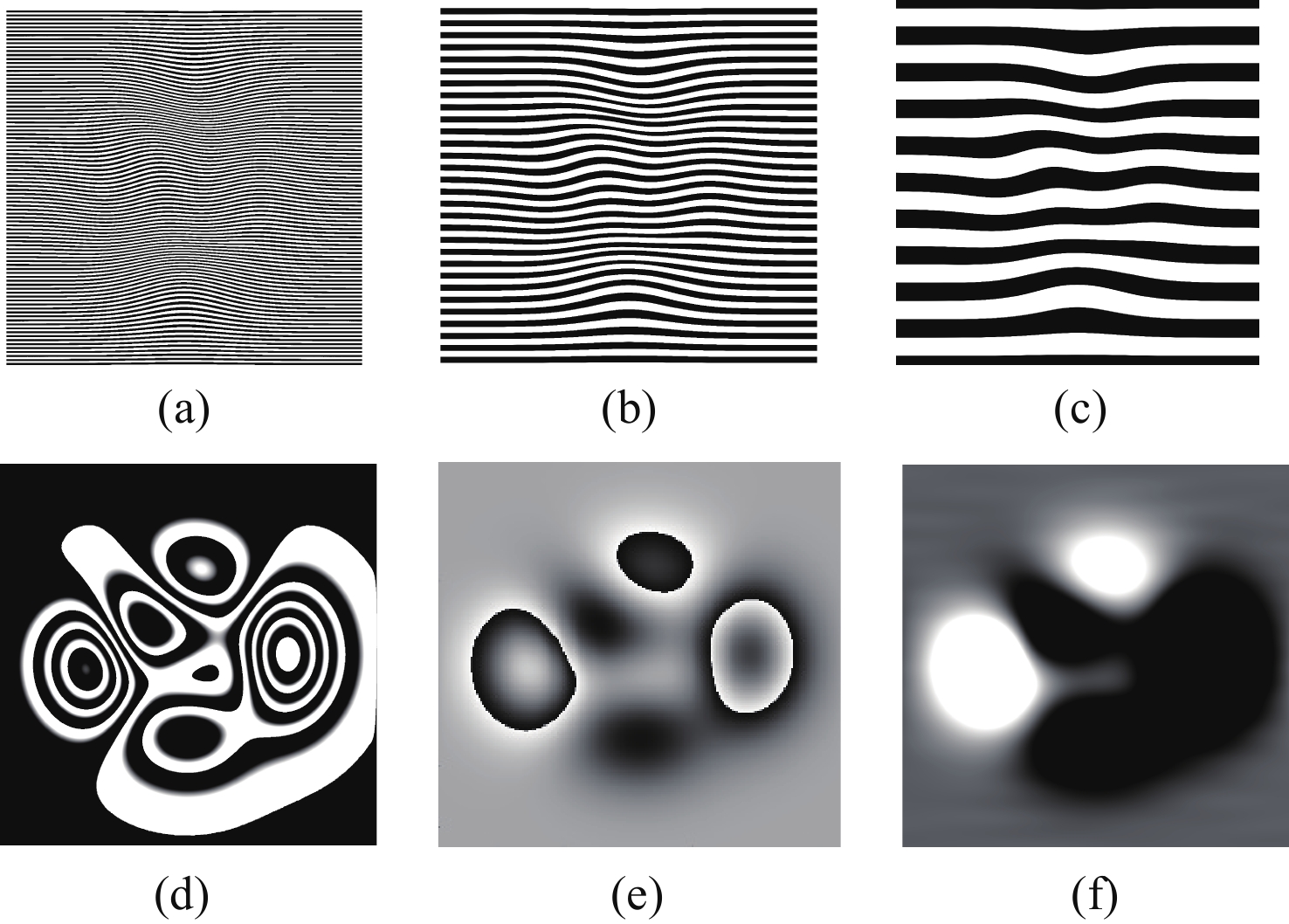
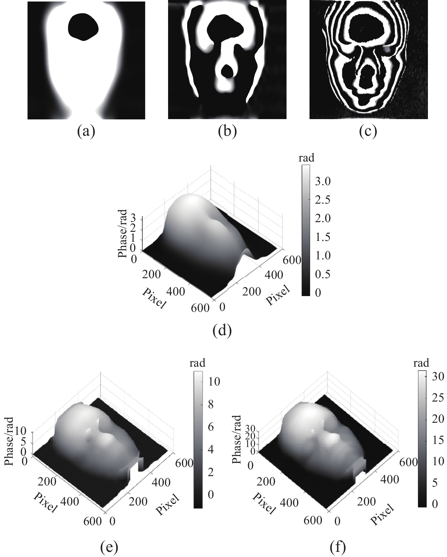
图 3 快速迭代滤波分离的高、中、低频条纹及傅里叶提取的高、中、低频相位。(a)高频条纹;(b)中频条纹;(c)低频条纹;(d)高频包裹相位;(e)中频包裹相位;(f)低频包裹相位
Figure 3. High, medium, and low-frequency moiré patterns separated by fast iterative filtering, along with the high, medium, and low-frequency phases extracted by Fourier transform. (a) high-frequency moiré pattern; (b) medium-frequency moiré pattern; (c) low-frequency moiré pattern; (d) wrapped phase of the high-frequency component; (e) wrapped phase of the medium-frequency component; (f) wrapped phase of the low-frequency component
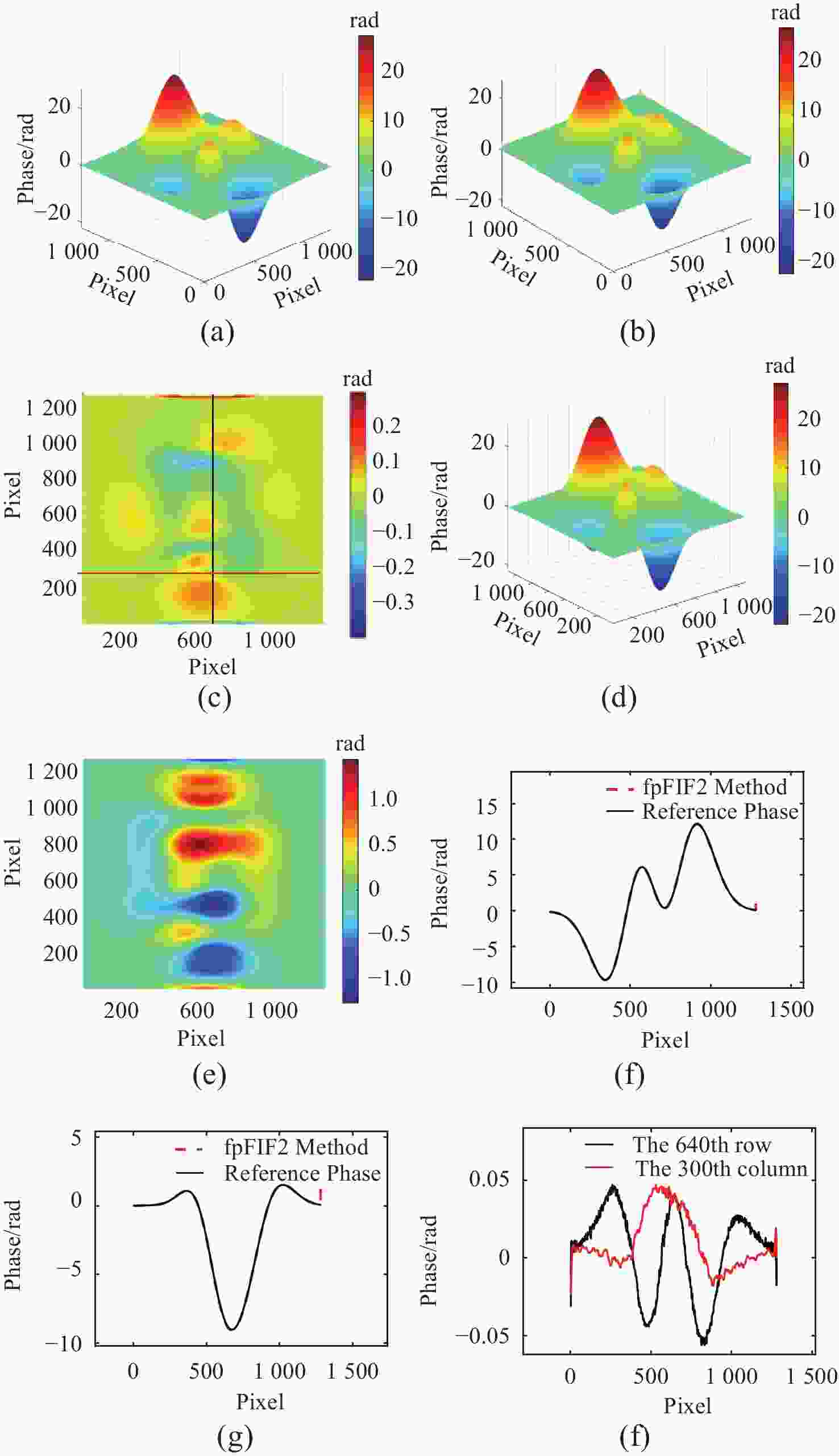
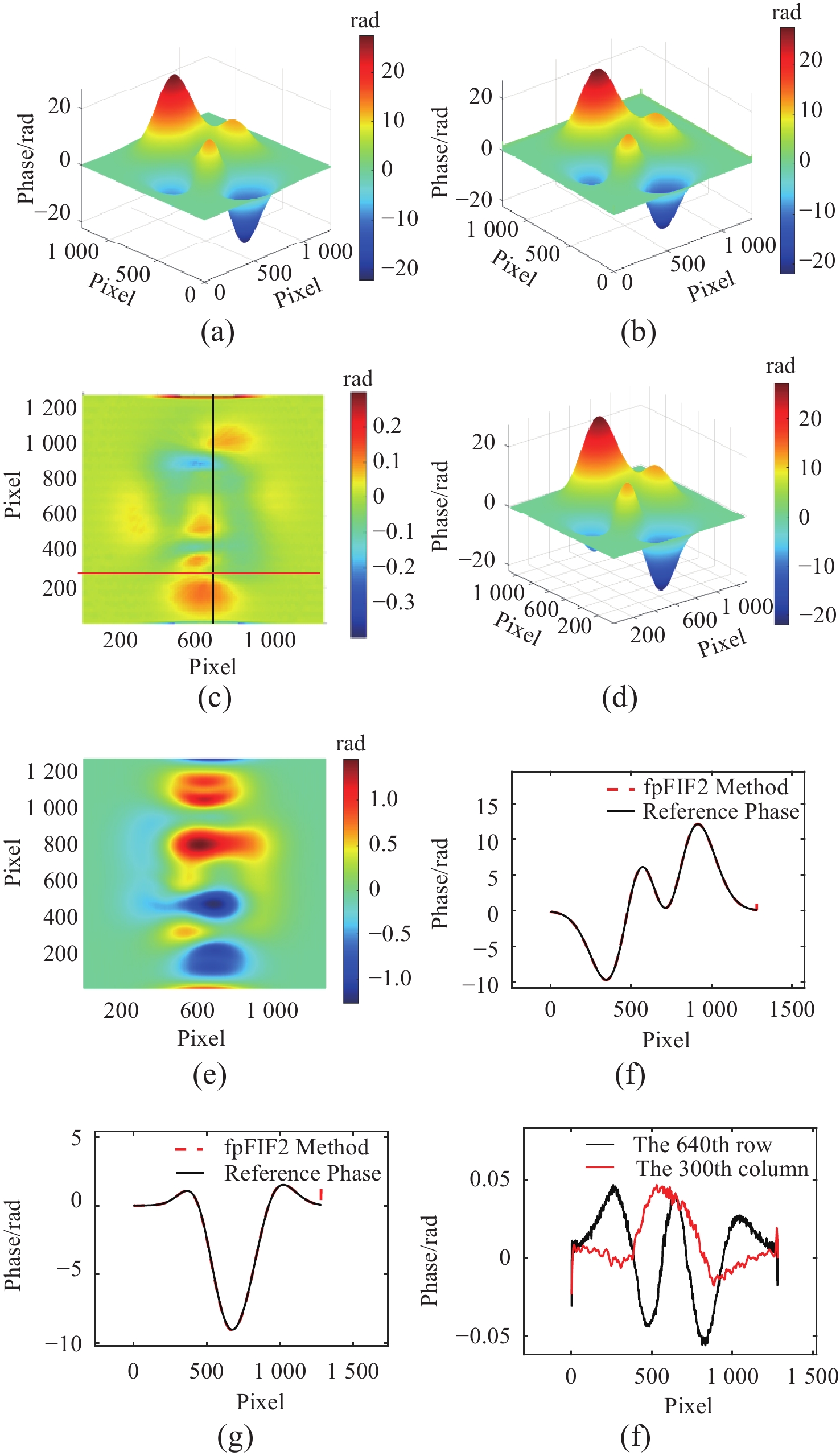
图 4 本文方法与FTP法求解的展开相位和参考相位对比。(a) 参考相位;(b) 本文方法展开相位;(c) 本文方法相位误差图;(d) FTP法展开相位;(e) FTP法相位误差图;(f) 参考相位与本文方法所求展开相位第640行相位数据、(g)第300列的相位数据及(h)第640行与第300列误差
Figure 4. Comparison of the proposed method with the FTP method for solving the expanded and reference phases. (a) reference phase; (b) expanded phase of the method in this paper; (c) phase error map of the method in this paper; (d) expanded phase using the traditional Fourier method; (e) phase error map of the traditional Fourier method; (f) comparison of the reference phase and the expanded phase obtained by the method in this paper for the phase data of the 640th row; (g) phase data of the 300th column, and (h) error of the 640th row and the 300th column
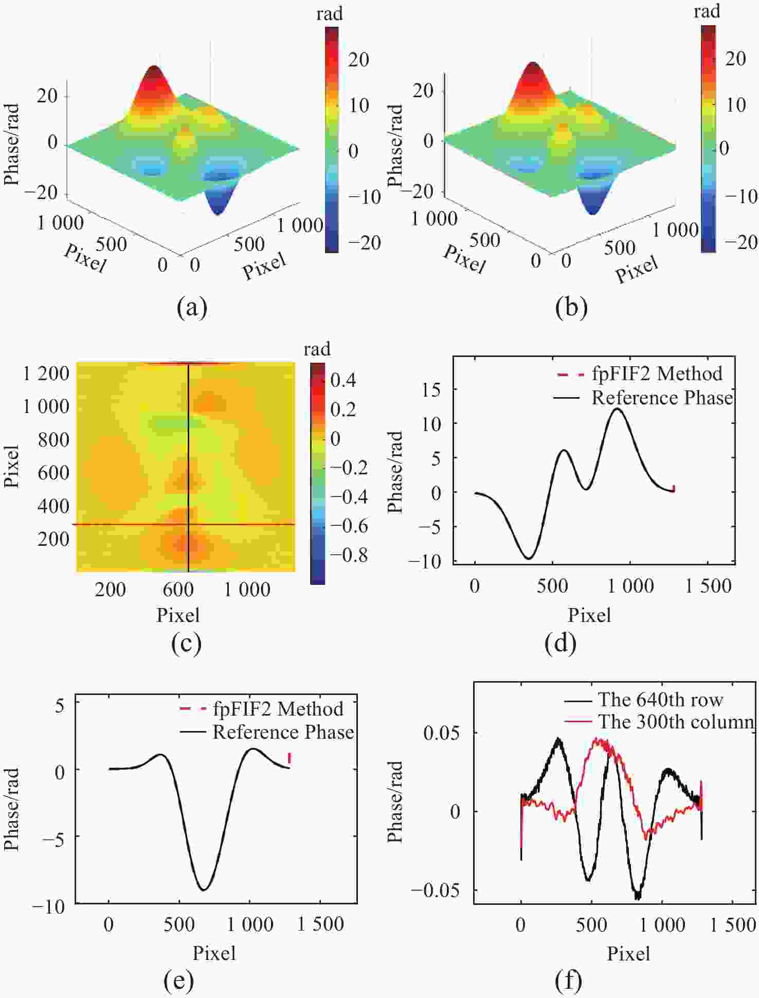
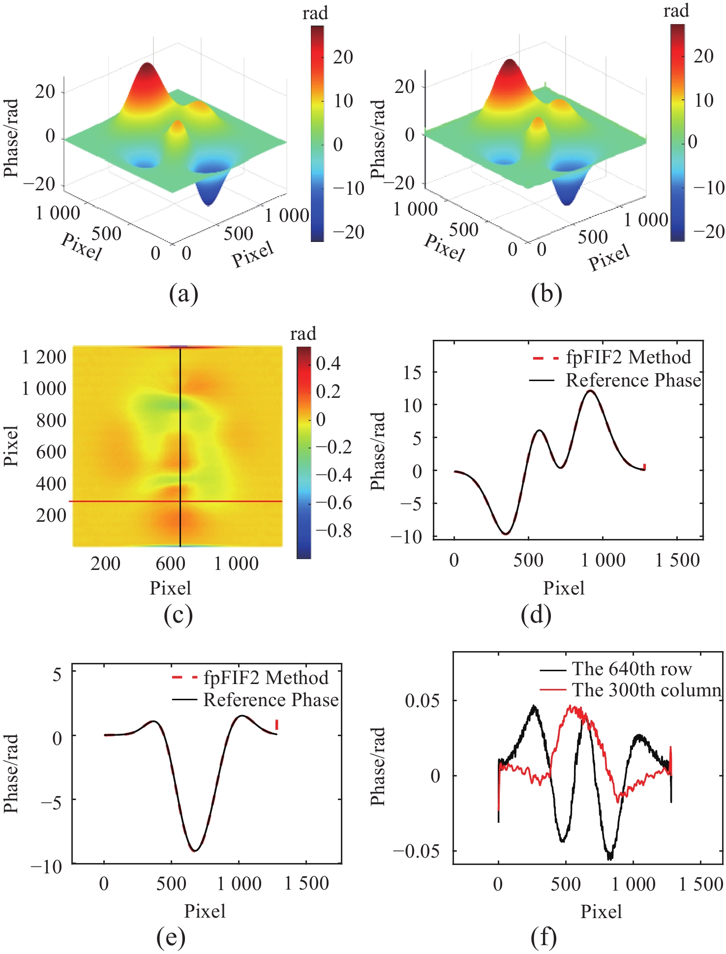
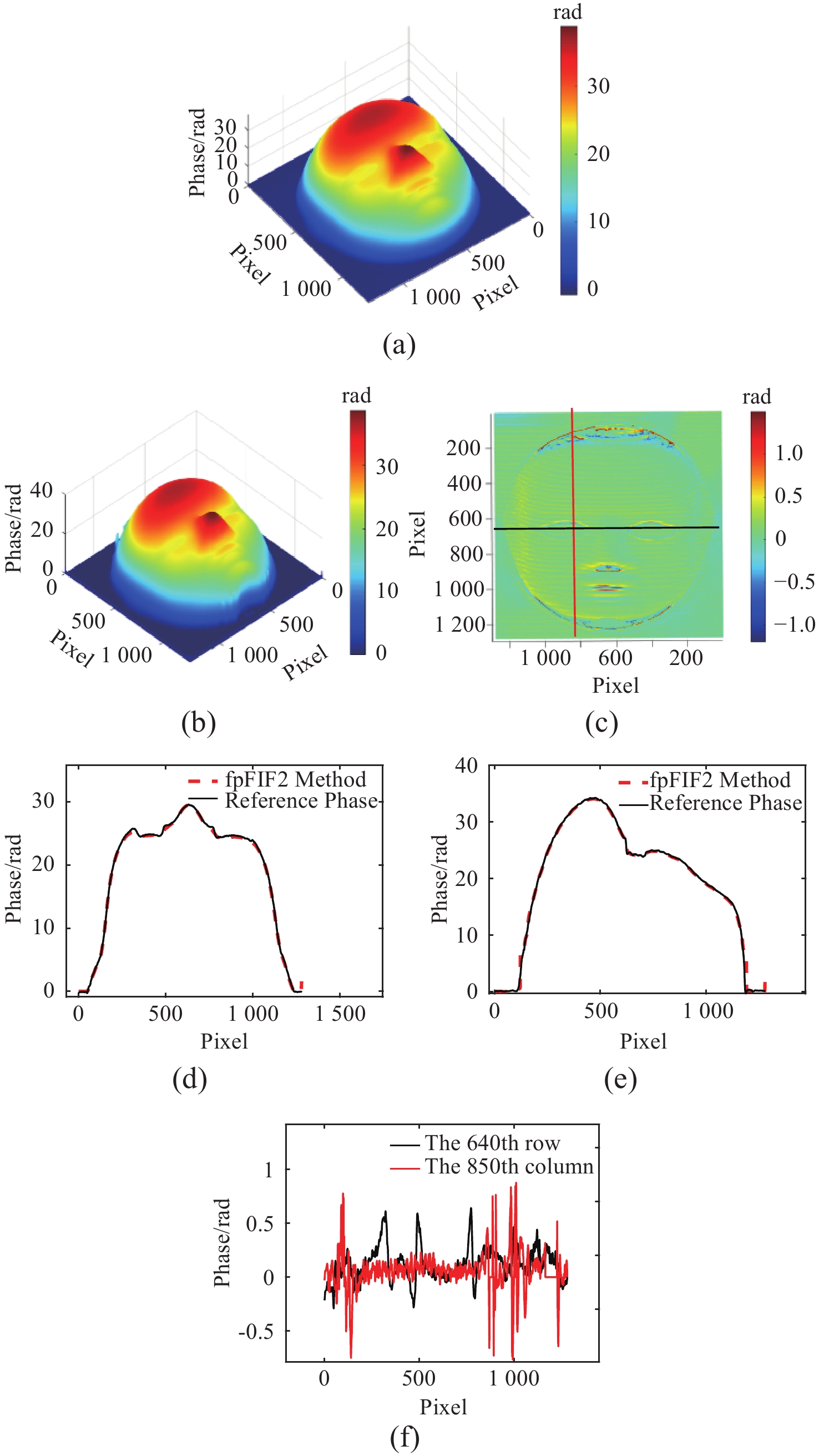
图 5 增大颜色耦合和噪声后(接近真实实验环境)参考相位和真实相位对比。(a) 参考相位;(b) 真实相位;(c) 参考相位与真实相位误差图;(d) 参考相位与真实相位第640行展开相位数据、(e)第300列展开相位数据及(f)第640行与第300列误差
Figure 5. After increasing color coupling and noise (close to the real experimental environment), the comparison between the reference phase and the real phase. (a) reference phase; (b) real phase; (c) error map between the reference phase and the real phase; (d) unwrapped phase data of the 640th row of the reference phase and the real phase; (e) unwrapped phase data of the 300th column and (f) error between the 640th row and the 300th column
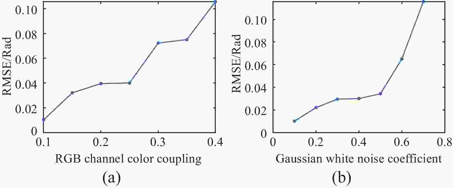
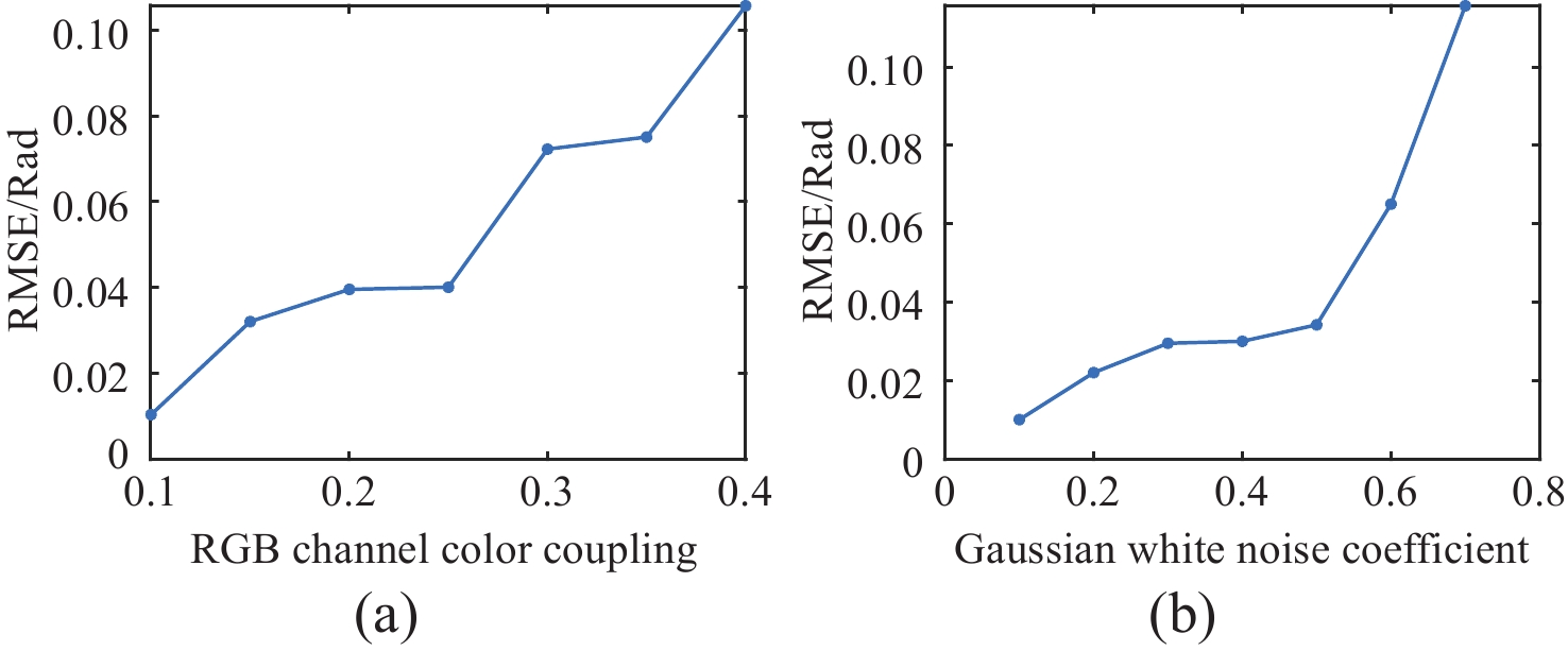
图 6 RGB通道的颜色耦合系数和噪声对均方根误差的影响。(a) 0.4高斯白噪声系数下(与真实环境噪声接近),RGB通道的颜色耦合系数与均方根误差的变化曲线图;(b) 与图4相同颜色耦合系数下,高斯白噪声与均方根误差的变化曲线图
Figure 6. The impact of color coupling coefficients and noise in RGB channel on Root Mean Square Error (RMSE). (a) variation of color coupling coefficient and RMSE under 0.4 Gaussian white noise (close to real environmental noise); (b) variation of Gaussian white noise and RMSE under the same color coupling coefficient as in Fig. 4
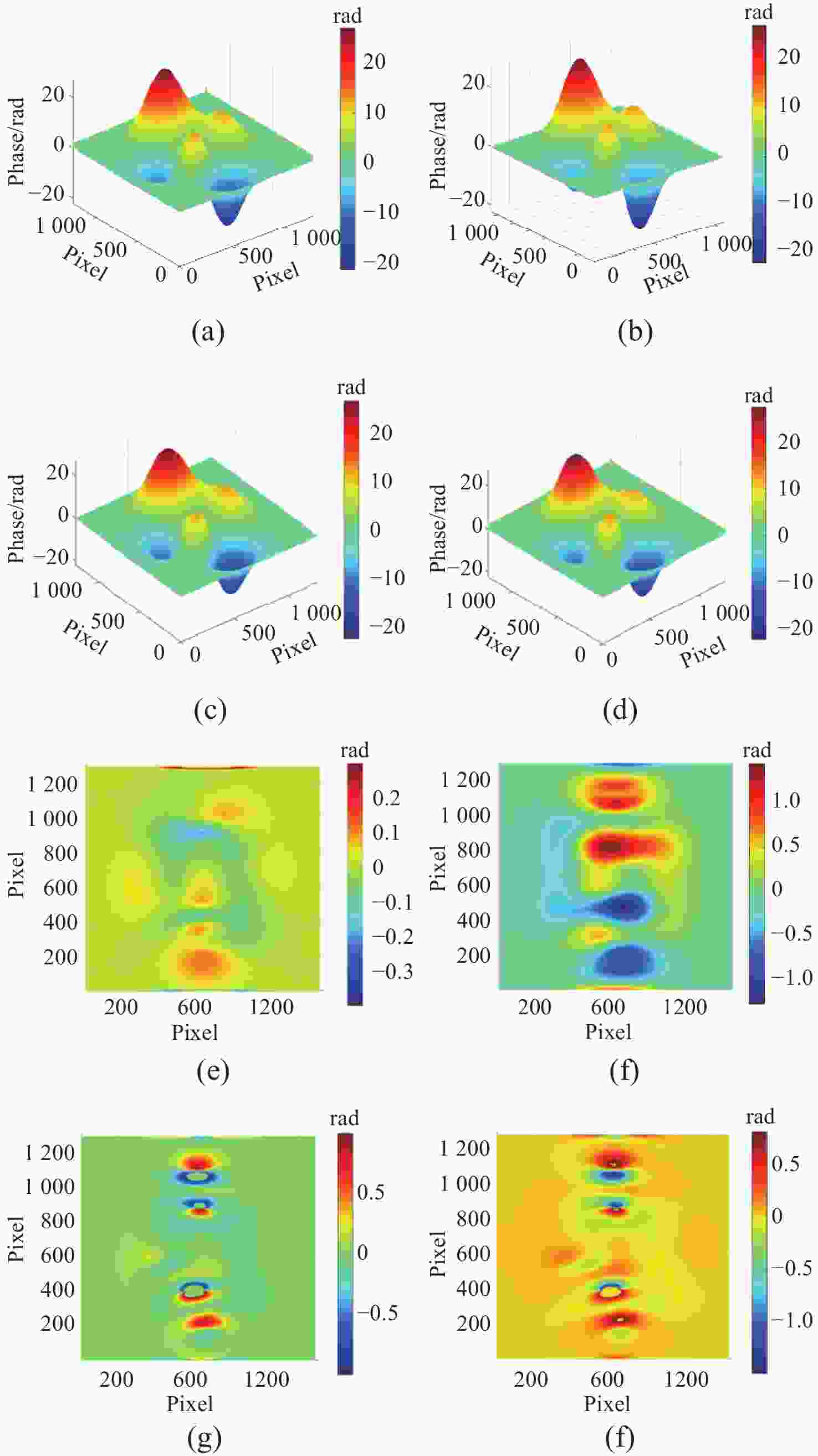
图 7 本文方法、FTP方法、VID方法、BEMD方法的仿真实验精度比较。(a) 本文方法、 (b) FTP方法、(c) VID方法及(d) BEMD方法的展开相位;(e) 本文方法、(f) FTP方法、(g) VID方法及(h) BEMD方法的展开相位与参考相位的误差图
Figure 7. Comparison of simulation experiment accuracy among the method in this paper, FTP method, VID method, and BEMD method. (a) method in this paper, (b) FTP method, (c) VID method, and (d) phase unwrapping of the BEMD method; (e) method in this paper, (f) FTP method, (g) VID method, and (h) error map of the unwrapped phase for the BEMD method compared to the reference phase
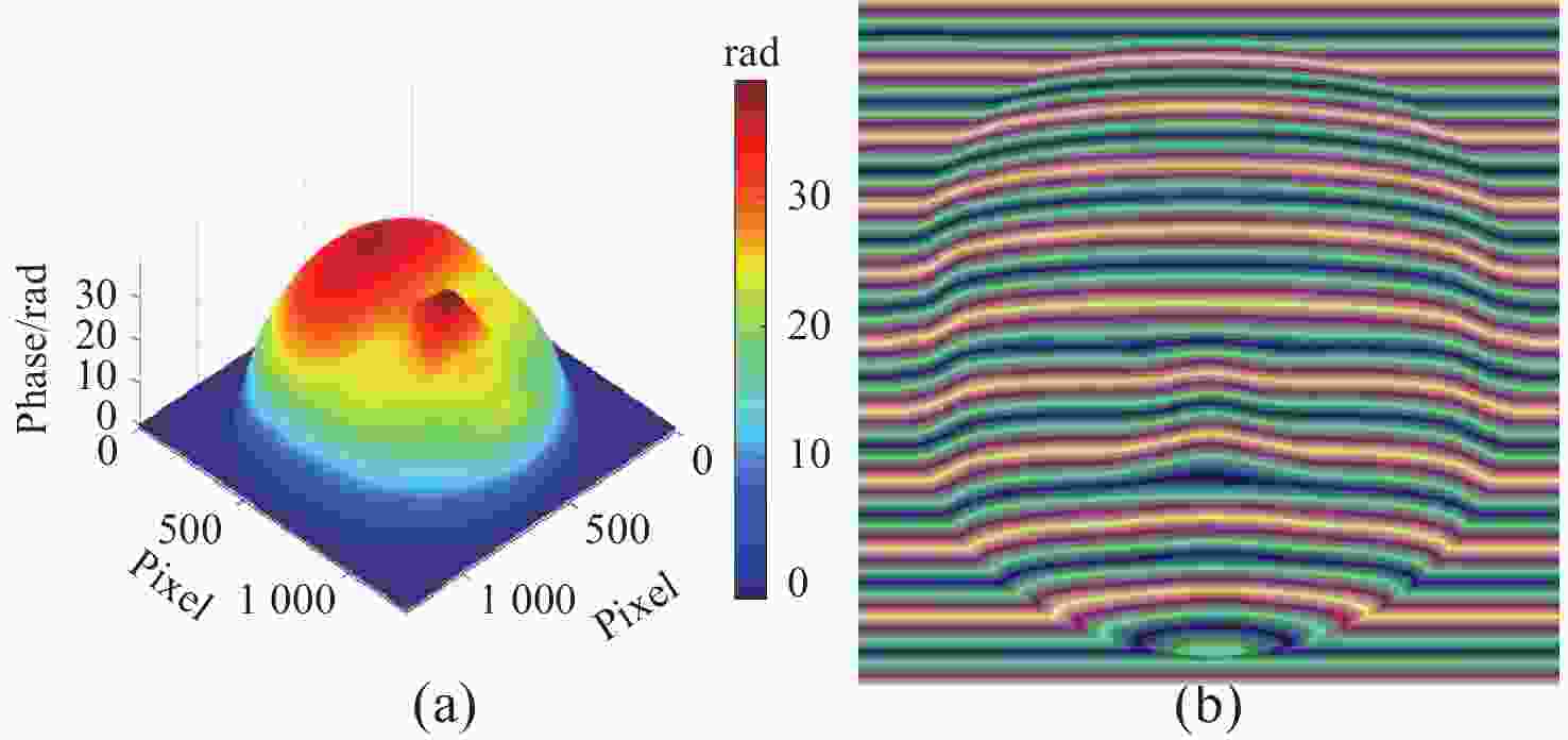
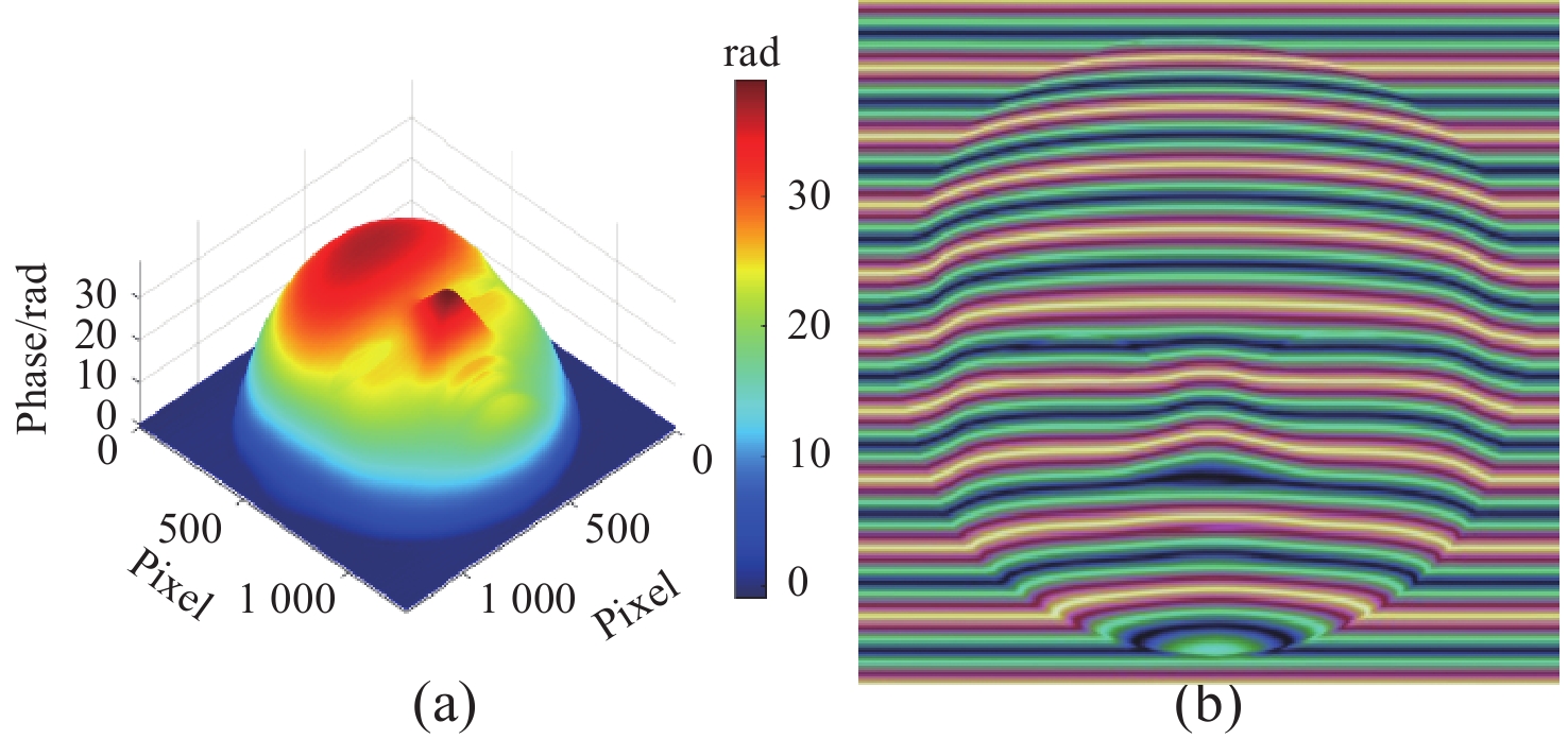
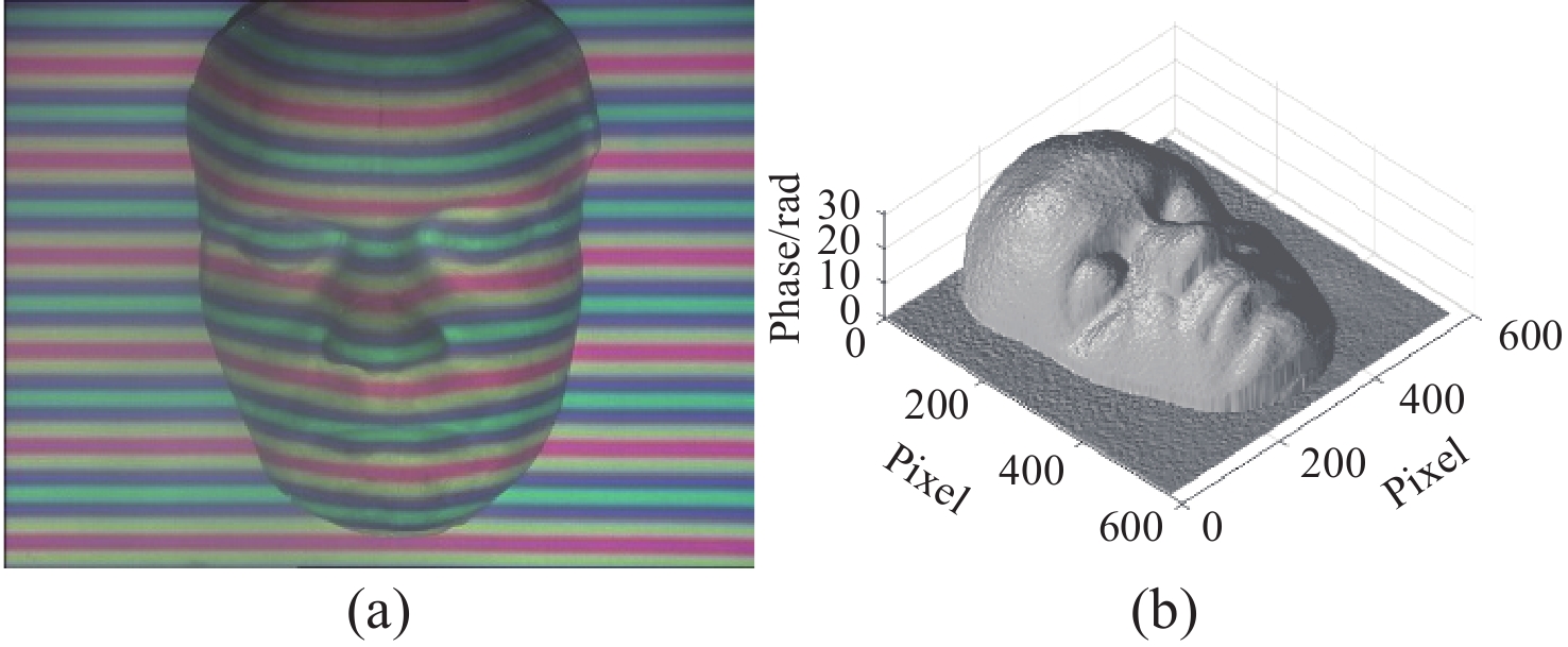
图 8 模拟人脸形变彩色条纹图和人脸参考相位。(a) 人脸参考相位;(b) 人脸形变彩色条纹;
Figure 8. Simulated facial deformation color fringe pattern and reference phase of the human face. (a) reference phase of the human face; (b) facial deformation color fringe pattern;
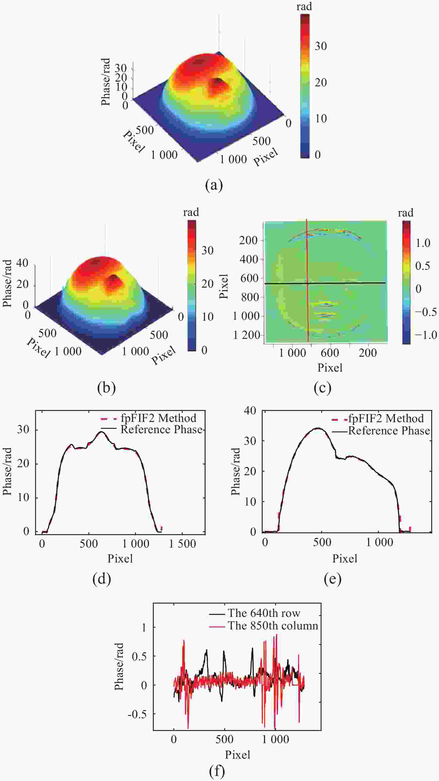
图 9 参考相位和真实相位对比。(a) 参考相位;(b) 真实相位;(c) 参考相位与真实相位误差图;(d) 真实相位与参考相位第640行数据、(e)第850列数据、(f)第640行和第850列误差
Figure 9. Comparison of reference phase and real phase. (a) reference phase;(b) real phase;(c) error map between reference phase and real phase; (d) data from the 640th row of real phase and reference phase; (e) data from the 850th column of real phase and reference phase; (f) error between the 640th row and 850th column
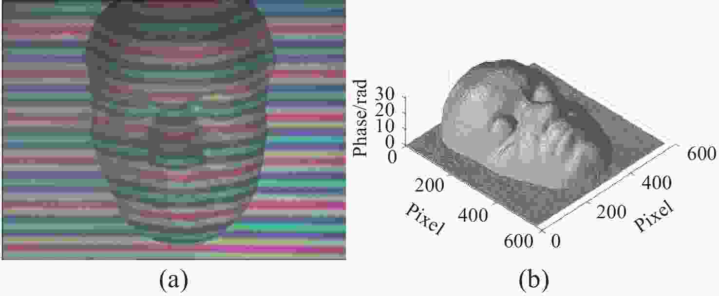
图 10 彩色调制条纹图与参考相位。(a) 人脸石膏调制彩色条纹图;(b) 相移法求解得到的展开相位当作参考相位
Figure 10. Color modulation fringe pattern and reference phase. (a) Color modulation fringe pattern of the facial plaster model; (b) Unwrapped phase obtained using the phase-shifting method as the reference phase
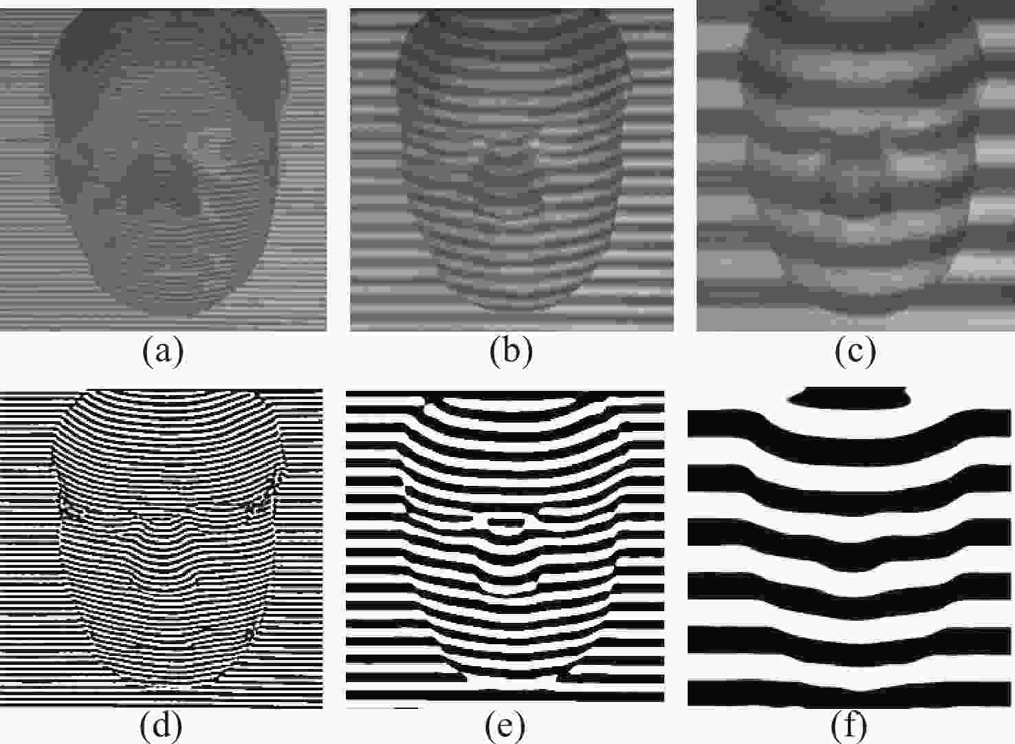
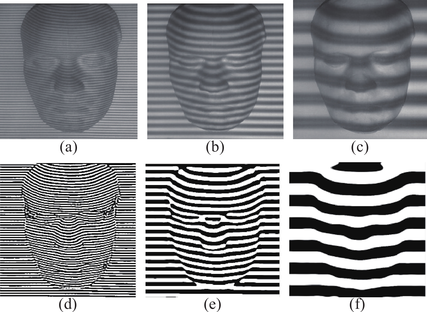
图 11 彩色条纹图初始RGB通道和快速迭代滤波分解后的RGB通道图像。(a) 初始高频通道;(b) 初始中频通道;(c) 初始低频通道;(d) fpFIF2分解后的高频通道、 (e)中频通道及(f)低频通道
Figure 11. Initial RGB channels of the color fringe image and the RGB channel images after fast iterative filtering decomposition. (a) initial high-frequency channel; (b) initial medium-frequency channel; (c) initial low-frequency channel; (d) high-frequency channel after fpFIF2 decomposition; (e) medium-frequency channel;(f) low-frequency channel
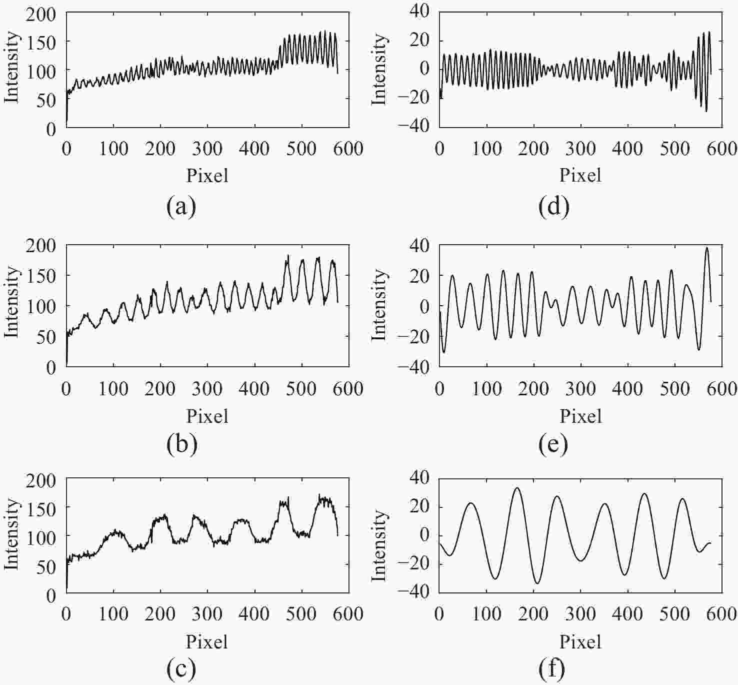
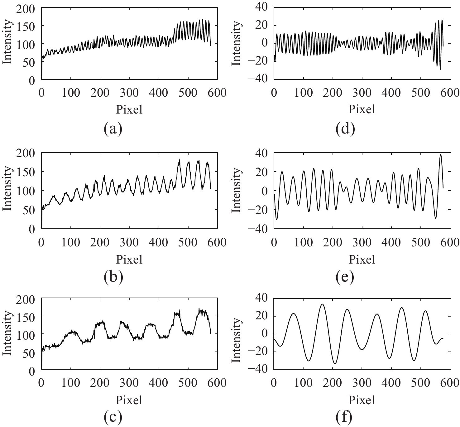
图 12 第256列变形条纹图初始RGB通道信号及fpFIF2分离的高、中、低载频项信号。(a) ~(c)为第256列初始条纹图低、中、高频通道信号分布;(d)~ (f)为fpFIF2分离后的第256列低、中、高频通道信号分布
Figure 12. Initial RGB channel signals of the deformation fringe image in column 256 and the high, medium, and low carrier frequency components separated by fpFIF2. (a) ~ (c) represent the distribution of the low-, medium-, and high-frequency channel signals of the initial fringe image in column 256; (d) ~ (f) represent the distribution of the low-, medium-, and high-frequency channel signals after separation by fpFIF2 in column 256
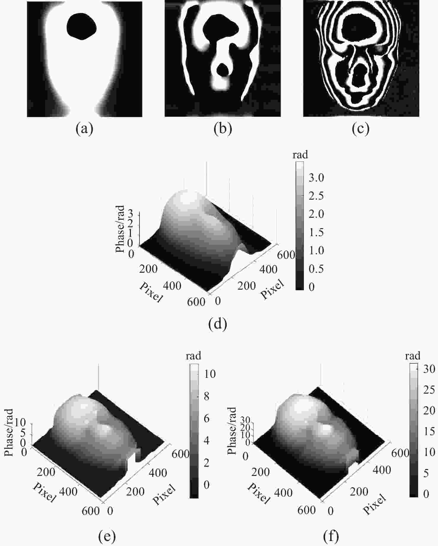
图 13 低、中、高载频包裹相位及低、中、高载频展开相位。(a)低频包裹相位;(b)中频包裹相位;(c)高频包裹相位;(d)低频展开相位;(e)中频展开相位;(f)高频展开相位
Figure 13. The phase of low-, medium-, and high-frequency wrapping, and unwrapping. (a) low-frequency wrapped phase; (b) Medium-frequency wrapped phase; (c) high-frequency wrapped phase; (d) low-frequency unwrapped phase; (e) medium-frequency unwrapped phase; (f) high-frequency unwrapped phase
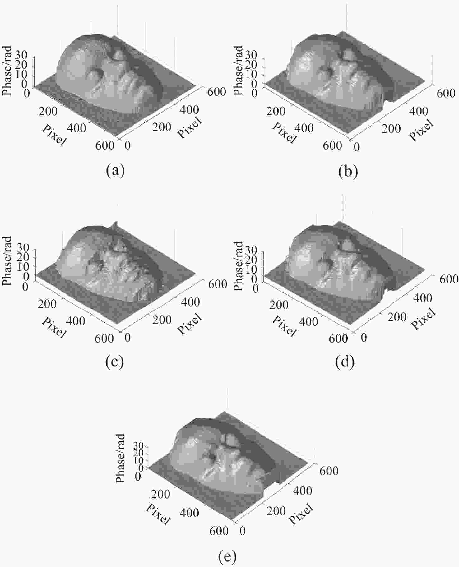
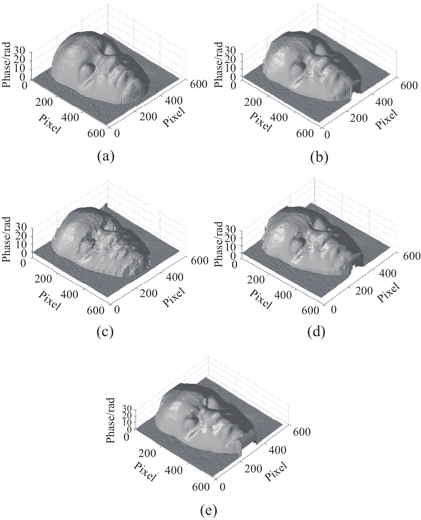
图 14 不同方法所求出的展开相位。(a) 四步相移法、 (b) 本文方法、 (c) FTP方法、 (d) 基于VID的彩色条纹投影方法及 (e) 基于BEMD的彩色条纹投影方法求出的展开相位
Figure 14. The unfolded phase obtained by different methods: (a) four-step phase shifting method, (b) method proposed in this paper, (c) FTP method, (d) VID-based color fringe projection method, and (e) BEMD-based color fringe projection method
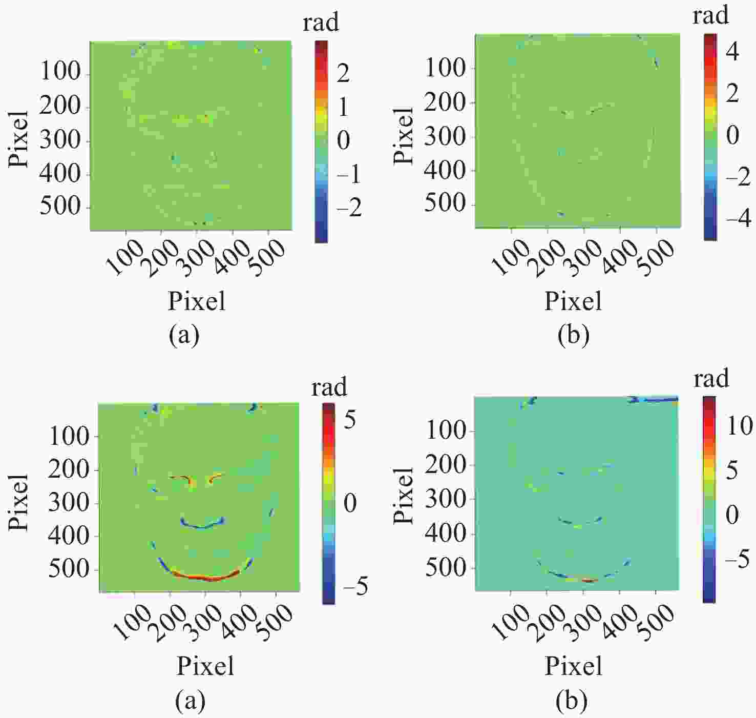
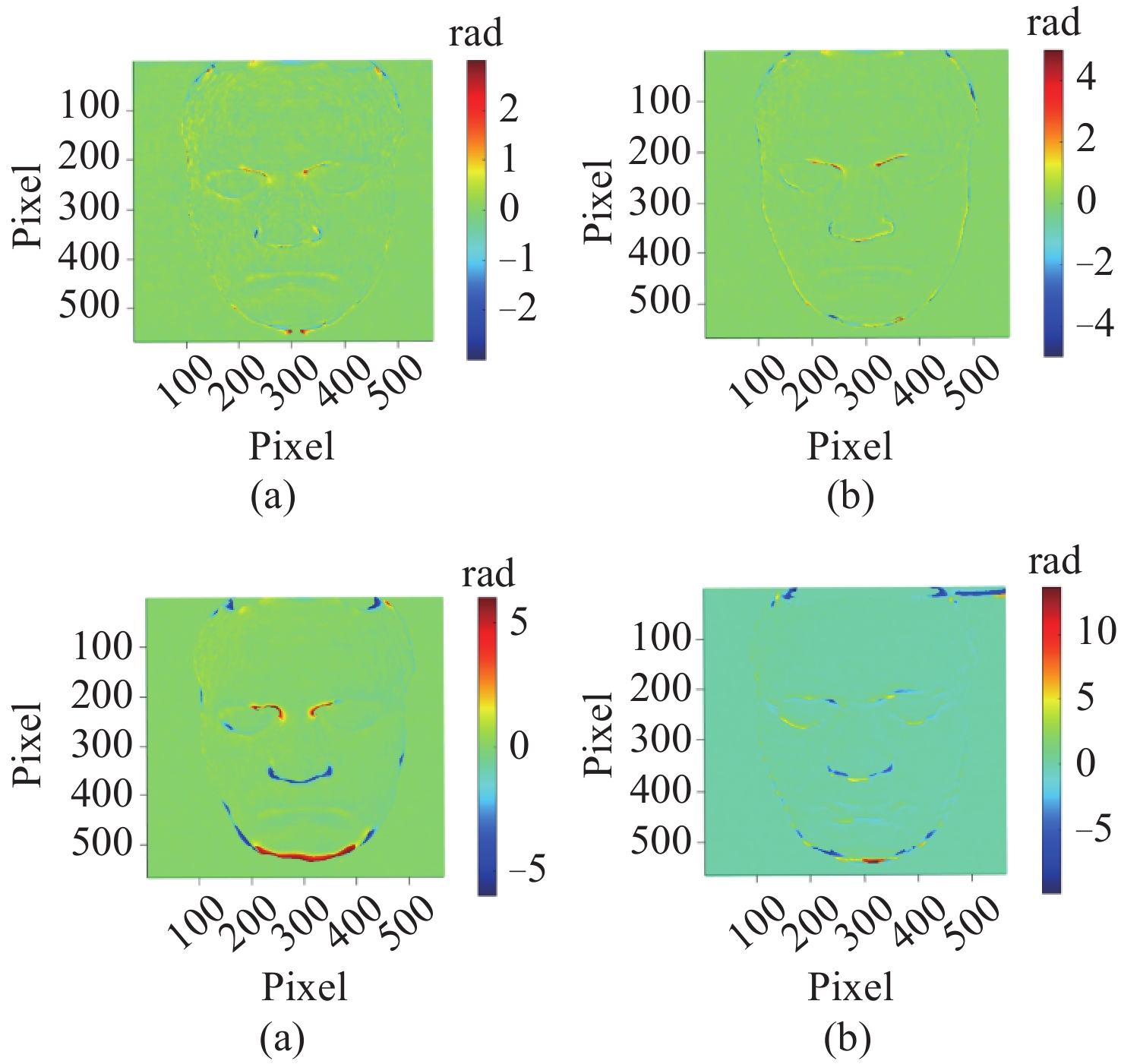
图 15 几种单帧方法与四步相移法的相位误差图。(a) 本文方法、(b) 基于VID的方法、 (c) 基于BEMD的方法及 (d) FTP方法与四步相移法的相位误差图
Figure 15. Phase error maps of several single-frame methods compared with the four-step phase shifting method. (a) method proposed in this paper; (b) VID-based method; (c) BEMD-based method; and (d) FTP method compared with the four-step phase shifting method
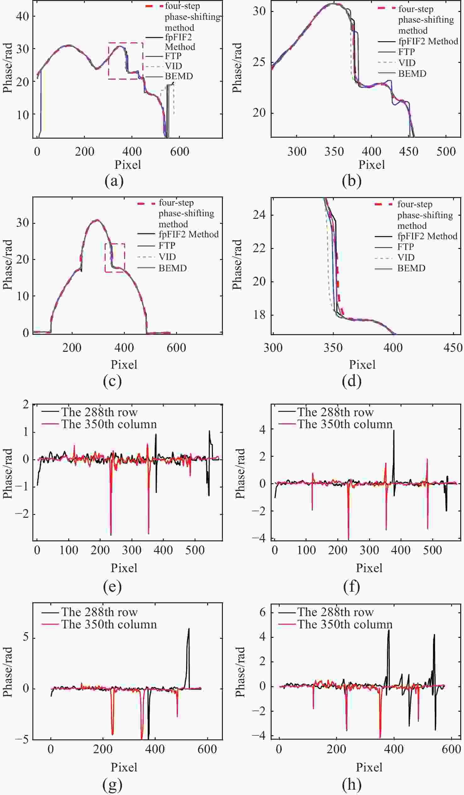
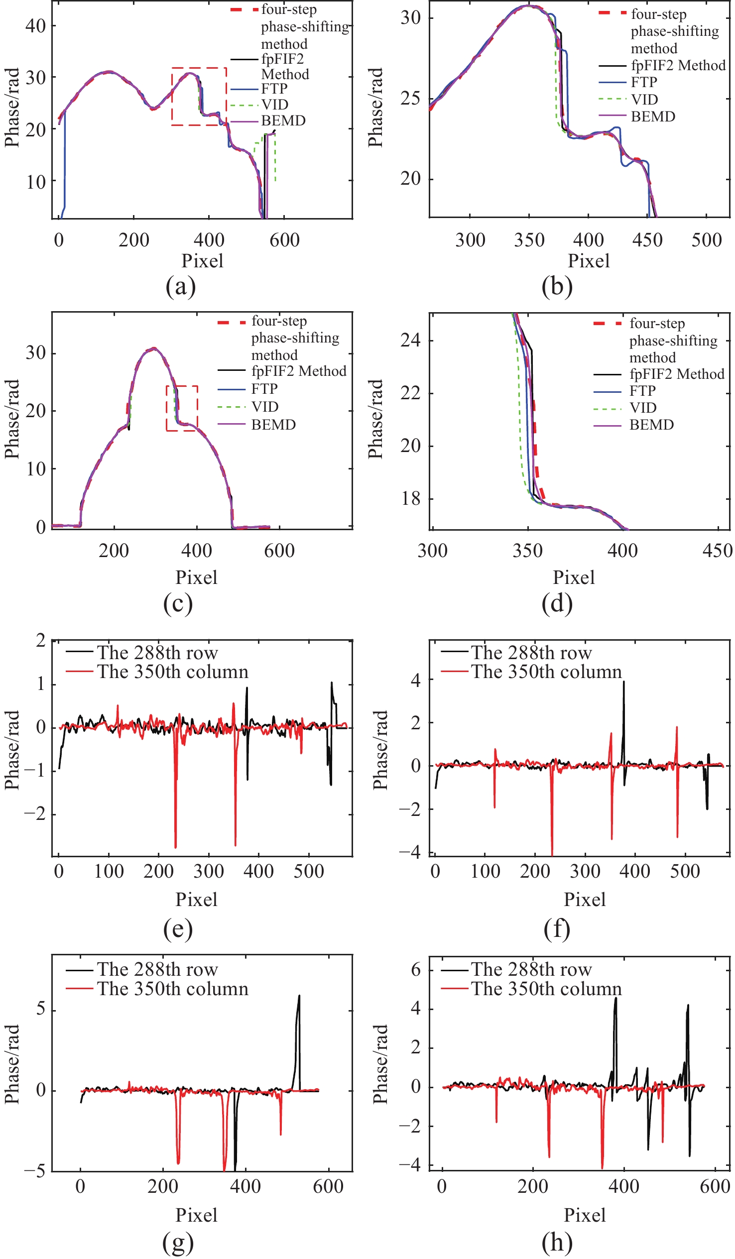
图 16 本文方法、基于VID方法、基于BEMD方法、FTP、四步相移法第288行和第350列展开相位数据及局部放大数据图。(a)上述几种方法第288行展开相位数据,其中黑色实线为本文方法;(b) 图(a) 鼻子处局部放大图;(c) 上述几种方法第350列展开相位数据;(d) 图(c)鼻子处局部放大图;(e) 本文方法、 (f) 基于VID的方法、 (g) 基于BEMD法及 (h) FTP方法与四步相移法第288行和第350列绝对误差
Figure 16. Phase data expansion and locally zoomed data for the 288th row and the 350th column using this method, VID-based method, BEMD-based method, FTP, and four-step phase-shifting method. (a) phase data expansion of the 288th row for the above methods, where the black solid line represents the method in this paper; (b) local zoomed-in image at the nose region in (a); (c) phase data expansion of the 350th column for the above methods; (d) local zoomed-in image at the nose region in (c); (e) absolute errors of the method in this paper; (f) VID-based method; (g) BEMD-based method, and (h) FTP method compared with the four-step phase-shifting method for the 288th row and the 350th column
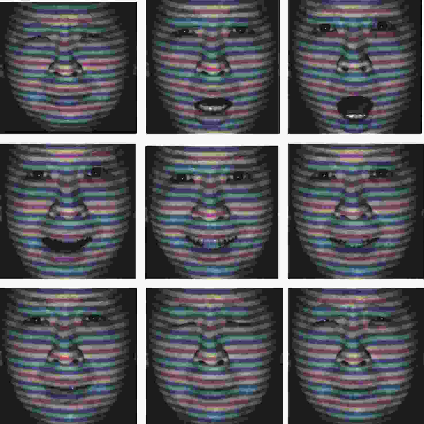
图 17 动态人脸表情变化视频的关键帧
Figure 17. Key frames from the videos of dynamic facial expression changes
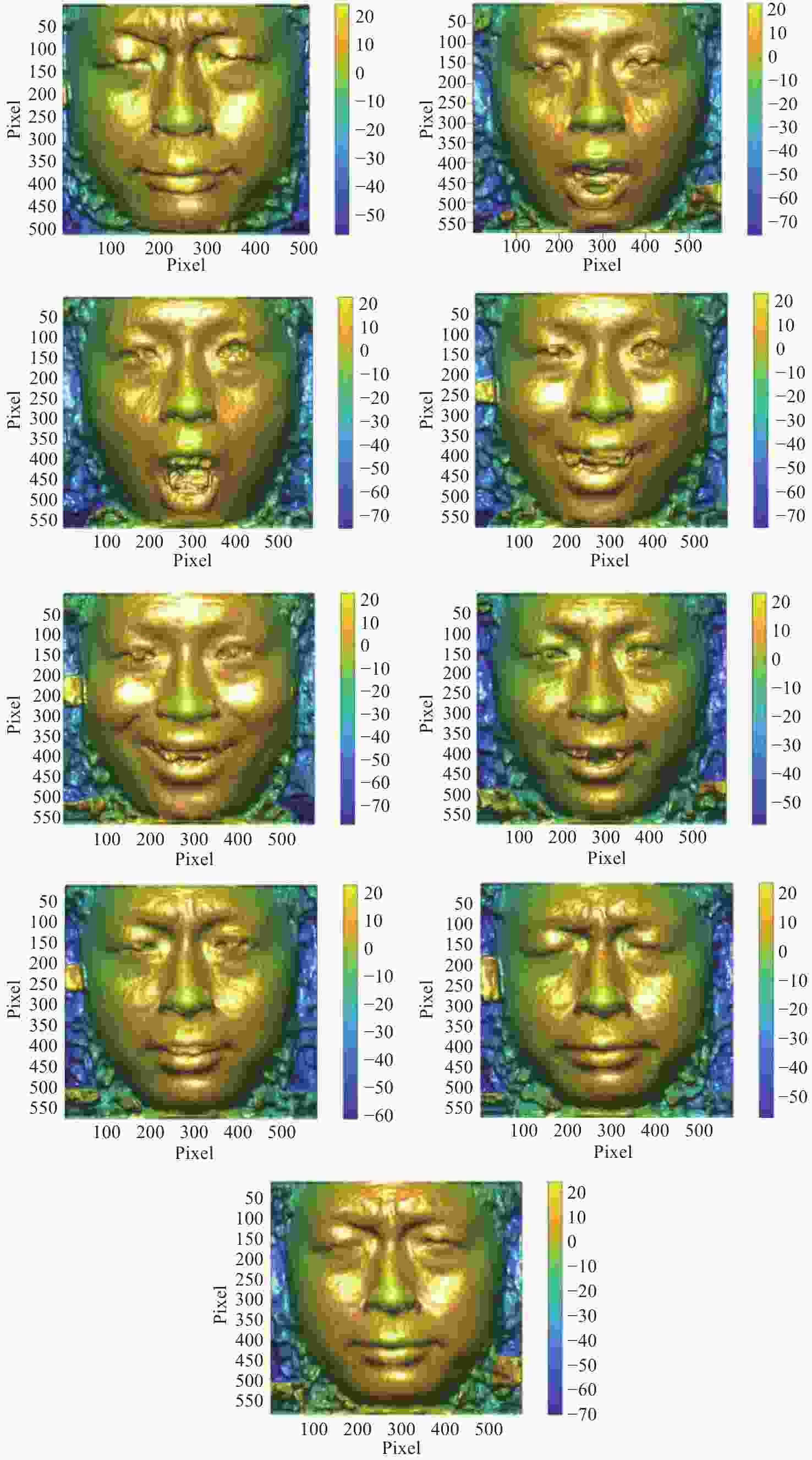
图 18 本文算法解调得人脸动态视频展开相位并取其表情变化关键几帧
Figure 18. Unwrapped phase of the facial dynamic video obtained by the proposed algorithm and selected key frames showing expression changes
表 1 本文方法、基于VID的方法、基于BEMD的方法、FTP方法和四步相移法的相位误差(均方根误差(RMSE))和第288行与第350行与参考值的标准差(SD)
Table 1. Phase errors (Root Mean Square Error (RMSE)) and standard deviation (SD) of the 288th and 350th rows compared to the reference values for the proposed method, VID-based method, BEMD-based method, FTP method, and four-step phase shift method
Method RMSE/rad 288 row-SD/rad 350 column-SD/rad fpFIF2 0.1736 0.1995 0.2112 VID 0.2062 0.4830 0.3236 BEMD 0.2512 0.4437 0.3579 FTP 0.8986 0.9616 0.4514  下载: 导出CSV
表 2 fpFIF2、VID及BEMD经验模式分解的速度对比
Table 2. Comparison of the speeds of fpFIF2, VID, and BEMD empirical mode decomposition
fpFIF2 VID BEMD Time/s 0.9612 36.2115 1.8265
下载: 导出CSV
-
[1] 李天宇, 刘昌文, 段发阶, 等. 线结构光三维形貌测量系统精度影响因素分析[J]. 光学学报,2024,44(21):2112001. doi: 10.3788/AOS241065LI T Y, LIU C W, DUAN F J, et al. Analysis of factors influencing accuracy in line-structured light three dimensional surface measurement systems[J]. Acta Optica Sinica, 2024, 44(21): 2112001. (in Chinese). doi: 10.3788/AOS241065 [2] XU J, ZHANG S. Status, challenges, and future perspectives of fringe projection profilometry[J]. Optics and Lasers in Engineering, 2020, 135: 106193. doi: 10.1016/j.optlaseng.2020.106193 [3] 王建华, 杨延西, 徐鹏, 等. 基于双2+1相移法的高动态范围三维测量[J]. 光学学报,2023,43(20):2012001. doi: 10.3788/AOS230809WANG J H, YANG Y X, XU P, et al. High dynamic range 3D measurement based on double 2+1 phase-shifting method[J]. Acta Optica Sinica, 2023, 43(20): 2012001. (in Chinese). doi: 10.3788/AOS230809 [4] ZHU ZH M, LIU H R, ZHANG J, et al. Calibration method of line-structured light sensors based on a hinge-connected target with arbitrary pinch angles[J]. Applied Optics, 2023, 62(7): 1695-1703. [5] 王永红, 张倩, 胡寅, 等. 显微条纹投影小视场三维表面成像技术综述[J]. 中国光学,2021,14(3):447-457. doi: 10.37188/CO.2020-0199WANG Y H, ZhANG Q, HU Y, et al. 3D small-field surface imaging based on microscopic fringe projection profilometry: a review[J]. Chinese Optics, 2021, 14(3): 447-457. (in Chinese). doi: 10.37188/CO.2020-0199 [6] SERVIN M, QUIROGA J A, PADILLA J M, et al. Fringe Pattern Analysis for Optical Metrology: Theory, Algorithms, and Applications[M]. Weinheim, Germany: Wiley-VCH Verlag GmbH & Co KGaA, 2014. [7] GORTHI S S, RASTOGI P. Fringe projection techniques: whither we are?[J] Optics and Lasers in Engineering, 2010, 48(2): 133-140. [8] AGARWAL N, WANG CH X, KEMAO Q. Windowed Fourier ridges for demodulation of carrier fringe patterns with nonlinearity: a theoretical analysis[J]. Applied Optics, 2018, 57(21): 6198-6206. doi: 10.1364/AO.57.006198 [9] PATORSKI K, POKORSKI K. Examination of singular scalar light fields using wavelet processing of fork fringes[J]. Applied Optics, 2011, 50(5): 773-781. doi: 10.1364/AO.50.000773 [10] ZHAO Q, TANG CH, MIN X, et al. Dynamic shape measurement for objects with patterns by Fourier fringe projection profilometry based on variational decomposition and multi-scale Retinex[J]. Applied Optics, 2021, 60(33): 10322-10331. doi: 10.1364/AO.438992 [11] QIAN J M, FENG SH J, LI Y X, et al. Single-shot absolute 3D shape measurement with deep-learning-based color fringe projection profilometry[J]. Optics Letters, 2020, 45(7): 1842-1845. doi: 10.1364/OL.388994 [12] RI S, AGARWAL N, WANG Q H, et al. Comparative study of sampling moiré and windowed Fourier transform techniques for demodulation of a single-fringe pattern[J]. Applied Optics, 2018, 57(36): 10402-10411. doi: 10.1364/AO.57.010402 [13] ZHONG J G, WENG J W, Phase retrieval of optical fringe patterns from the ridge of a wavelet transform[J]. Optics Letters, 2005, 30(19): 2560-2562. [14] ZHONG J G, WENG J W. Spatial carrier-fringe pattern analysis by means of wavelet transform: wavelet transform profilometry[J]. Applied Optics, 2004, 43(26): 4993-4998. doi: 10.1364/AO.43.004993 [15] RIVERA M, HERNANDEZ-LOPEZ F J, GONZALEZ A. Phase unwrapping by accumulation of residual maps[J]. Optics and Lasers in Engineering, 2015, 64: 51-58. doi: 10.1016/j.optlaseng.2014.07.005 [16] ZHANG Q C, HAN Y, WU Y S. Comparison and combination of three spatial phase unwrapping algorithms[J]. Optical Review, 2019, 26(4): 380-390. doi: 10.1007/s10043-019-00513-7 [17] SHEN M H, HWANG C H, WANG W CH. Using higher steps phase-shifting algorithms and linear least-squares fitting in white-light scanning interferometry[J]. Optics and Lasers in Engineering, 2015, 66: 165-173. doi: 10.1016/j.optlaseng.2014.09.004 [18] HE W, XIA L, LIU F. Sparse-representation-based direct minimum L p-norm algorithm for MRI phase unwrapping[J]. Computational and Mathematical Methods in Medicine, 2014, 2014(1): 134058. [19] WU H T, CAO Y P, AN H H, et al. A novel phase-shifting profilometry to realize temporal phase unwrapping simultaneously with the least fringe patterns[J]. Optics and Lasers in Engineering, 2022, 153: 107004. doi: 10.1016/j.optlaseng.2022.107004 [20] ROGALSKI M, PIELACH M, CICONE A, et al. Tailoring 2D fast iterative filtering algorithm for low-contrast optical fringe pattern preprocessing[J]. Optics and Lasers in Engineering, 2022, 155: 107069. doi: 10.1016/j.optlaseng.2022.107069 [21] HUANG N E, SHEN ZH, LONG S R, et al. The empirical mode decomposition and the Hilbert spectrum for nonlinear and non-stationary time series analysis[J]. Proceedings of the Royal Society of London. Series A: Mathematical, Physical and Engineering Sciences, 1998, 454(1971): 903-995. doi: 10.1098/rspa.1998.0193 [22] TRUSIAK M, CYWIŃSKA M, MICÓ V, et al. Variational Hilbert quantitative phase imaging[J]. Scientific Reports, 2020, 10(1): 13955. doi: 10.1038/s41598-020-69717-1 [23] HU M L, CHEN Y, HU H L, et al. Single frame digital phase-shift fringe projection profilometry based on symmetry transform[J]. Optical Engineering, 2024, 63(10): 104106. [24] 冯维, p徐仕楠, 王恒辉, 等. 逐像素调制的高反光表面三维测量方法[J]. 中国光学,2022,15(3):488-497. doi: 10.37188/CO.2021-0220FENG W, XU S N, WANG H H, et al. Three-dimensional measurement method of highly reflective surface based on per-pixel modulation[J]. Chinese Optics, 2022, 15(3): 488-497. (in Chinese). doi: 10.37188/CO.2021-0220 -


 下载:
下载:


计量
- 文章访问数: 130
- HTML全文浏览量: 57
- PDF下载量: 6
- 被引次数: 0
